Triggers

Triggers are modules of the VME Crates of Gammasphere's DAQ system, along with IOCs and digitizers. They communicate directly with digitizers in the VME Crates. Triggers are the “decision makers” of the DAQ system, and decide what data is worthy of keeping and sending out to EPICS. There are two types of triggers: system triggers and router triggers. Gammasphere's DAQ system has only one system trigger, but each VME crate has one router trigger, meaning the DAQ system overall has one system trigger and four router triggers. The system trigger also connects to a VME Fiber Expander, which allows external detector systems based on the same trigger system to be interconnected with Gammasphere’s trigger system (such as Argonne Gas-Filled Analyzer). Figure 1 shows how this is contained in each relay rack. Note that Figure 1 does not represent what the VME crate looks like in real life. It only shows what's actually in the crate, and not how it's laid out. Figure 2 of the collector box page shows what the trigger layout looks like within each VME crate.
The trigger system receives the signals from the detectors as bits and processes them in pairs per detector. Coincidence logic within the trigger system identifies GeCenter and BGOSum bits that occur within a programmable overlap time, issuing “veto” signals back to the channels of the digitizers where such overlap occurs. These Veto signals are used to delete the coincident (“dirty”) events prior to such events being made available for the system trigger. The routers present the "clean" signals to the "system" trigger (formerly known as the master trigger). An acceptance message from the system trigger contains information about the event, which is then broadcasted out to registers in digitizers before going to the IOCs for data readout. In a sense, the router triggers "pre-filter" the signals to send to the system trigger.
Implementation of the electric honeycomb requires that fast discriminator bits from the 7 BGO segments of each detector (six shields plus back plug), plus the six individual BGO discriminator bits that are face-to-face with the BGO shields, be combined. This requires implementation of discriminator logic within the pickoff card, with collection of the 13 bits for each of the detectors and generation of 110 ‘scatter’ bits, one per detector. This vector of ‘scatter’ bits must then be transmitted to the trigger system sufficiently fast to participate in the aforementioned coincidence logic that generates event veto signal.
Trigger EDM Screens
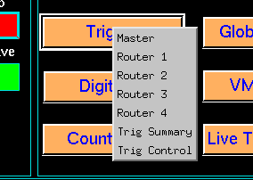
The EDM screens allow a user to monitor and control trigger processes. Below is a clickable image of the different screens available for trigger modules. You may also click on the section title to view the page that contains an image of the screen below and links it to relevant screens.