Collector Box
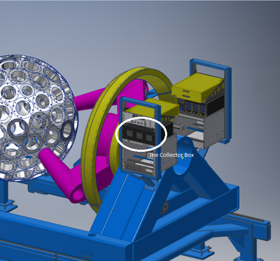
As a part of Gammasphere's upgraded DAQ system, a new "collector box" has been added. The collector box collects and maps all analog signals for up to 30 detectors, coming from the pickoff card in the SBX to the collector, and being output to the digitizers. For concepts like "electric honeycomb", the collector box implements distinct hardware to accurately route signals to the digitizer. It does this this by utilizing time synchronization with its access to the trigger system to ensure that the correct set of samples are used for the reconstruction of each BGO waveform. Control and monitoring of Gammasphere's modules are maintained with the help of the collector box, using EPICS IOC. It provides power to individual SBX units via a singular 48V input from the power supply (above the circled collector box in the image to the right).
The collector box was created to replace the system that preceded it, known as VXI crates. They consisted of multiple boards and racks, including over a hundred heavy, 60-foot multi-conductor cables that were draped all around Gammasphere. Detector slope boxes were connected directly to an entirely separate system called the VXI system, which would convert the signals to digitizer-readable differential signals before sending them off to "VXI digitizers". The VXI system had an entire "shack" designated to it, whereas the collector box upgrade can now be attached directly to Gammasphere's chassis and contain the DAQ system near the detectors. The previous system took up physical space within the room and presented a heat issue as well as multiple obsolescence risks and possibilities of power supply failure. The collector box eliminates these risks, and physically and digitally optimizes the overall system.
Collector Box Hardware
Throughout Gammasphere

Figure 1 shows a hemisphere of Gammasphere, and two of the collector boxes placed on it. On the other side of Gammasphere, there are another two collector boxes with the rest of the DAQ (the full picture is displayed on the DAQ system page). This is because Gammasphere has four pairs of collector boxes and VME crates (along with the power supply), each of which power and receive data from approximately 30 detectors. Figure 2 shows all of this from an above point of view; an "unfolded” drawing of how this mapping looks when viewing collectors and VME crates from their “active sides” where connections happen. Each collector box is shown (in the diagram) from the connector side, where cables are plugged in from the collector box to each SBX for power output. The output is accomplished using the same cable interfaces as used for the analog signal path, slow control-and-monitoring and all other detector functionality. All four collector boxes of Gammasphere are paired with their VME crate from their "active side", where the arrangement of digitizers, IOCs, and trigger modules are carefully placed. The collector boxes are labeled with the “GS#” they appear as in EPICS, with even “GS” numbers on the south hemisphere and odd “GS” numbers on the northern hemisphere. The semicircle “N” in Figure 2 represents the Gammasphere’s northern hemisphere, while “S” represents Gammasphere’s southern hemisphere. The compass directions in purple (NE, NW, SE, SW) are as in the current in-front-of-AGFA position. The collector boxes and VME crates are flipped right-to-left when comparing East versus West because the collector boxes are rotated 180 degrees in the birds’ eye view. Note that Figure 2 is giving a closeup of the system, but Figure 1 represents what the DAQ system actually looks like in real life. Although not shown in the Figure 2 diagram, each collector box also provides a connection for hooking up the alarm and status outputs from the external 48V DC supply, so that the collector can make that data available to the control system via the EPICS interface.
In Each Collector Box

Observing Figure 2, one can note from each collector box that there are 30 output cables, each boxed in the diagram into groups of three. This is because there are six FPGAs (field-programmable gate arrays) programmed to handle 5 detectors at a time in units called "stripes". The Collector Box maps the four differential signals from the Pickoff to specified digitizer channels, while distributing 48V Power to individual SBX Units. Built-in ground fault circuits periodically monitor continuity between the DVI cable shield and Earth ground, as ground loops are another known source of degraded performance. A distinct FPGA collects all BGO discriminator bits, calculates the Electric Honeycomb for nearest neighbor Compton Suppression, and sends the information to a dedicated router of the trigger system via fiber optic cable. This Electric Honeycomb increases Compton suppression by up to 10% @ 1 MeV. With the Electric Honeycomb now supported by a distinct Trigger module, two of the four digitized channels have multiple options for readout. The Ge center and BGO sum will always remain fixed, but the other two can be assigned to the Ge sides, the BGO Hit Pattern, or to a copy of the Ge center at a fixed energy range (of 8 or 20 MeV). The collector box routes these values to the "front boards" to the digitizers in the VME Crates.
Go back to DAQ system