The Pickoff Card: Difference between revisions
No edit summary |
|||
| Line 6: | Line 6: | ||
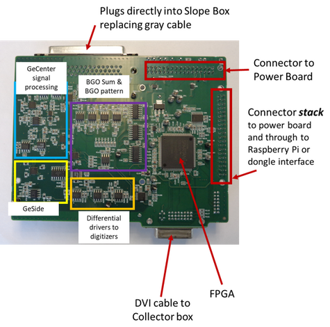
Figure 1 shows the pickoff card, a circuit board with sections allocated to each of its functions. Parts of the pickoff card are dedicated to the processing of specific [[Detector Signals|signals]], like the Ge center, Ge sides, and BGO sum and BGO pattern. It is designed to stack up with the SBX power board, and has protruding connectors on two different sides to do so. It has connectors for an optional Raspberry Pi, which is meant to enable standalone detector operation. DVI cables are attached to the bottoms of pickoff cards for the power input from the collector box. The FPGA of the SBX pickoff performs automated scanning of the Preamp, the Power Board and the Slope Box continuously in the background using scan programs stored in read-only memory. At startup, the EEPROMs of both the Preamp and the Dongle are also read. Within the pickoff firmware, scanner machines run these scan programs with the help of transactor machines that perform individual reads/writes tailored to the specific communications protocols of each device (speed, signal types, etc). All scanners can be paused to allow EPICS to manually insert commands to the transactors to set any detector device to new values. The status information collected by all these scanners is then written into a dual-port RAM by an arbiter machine. Values in the dual-port RAM are read by EPICS just like any register of the pickoff FPGA, hiding all device-specific timing from EPICS. | Figure 1 shows the pickoff card, a circuit board with sections allocated to each of its functions. Parts of the pickoff card are dedicated to the processing of specific [[Detector Signals|signals]], like the Ge center, Ge sides, and BGO sum and BGO pattern. It is designed to stack up with the SBX power board, and has protruding connectors on two different sides to do so. It has connectors for an optional Raspberry Pi, which is meant to enable standalone detector operation. DVI cables are attached to the bottoms of pickoff cards for the power input from the collector box. The FPGA of the SBX pickoff performs automated scanning of the Preamp, the Power Board and the Slope Box continuously in the background using scan programs stored in read-only memory. At startup, the EEPROMs of both the Preamp and the Dongle are also read. Within the pickoff firmware, scanner machines run these scan programs with the help of transactor machines that perform individual reads/writes tailored to the specific communications protocols of each device (speed, signal types, etc). All scanners can be paused to allow EPICS to manually insert commands to the transactors to set any detector device to new values. The status information collected by all these scanners is then written into a dual-port RAM by an arbiter machine. Values in the dual-port RAM are read by EPICS just like any register of the pickoff FPGA, hiding all device-specific timing from EPICS. | ||
== The VXI Pickoff Card (Before Upgrades) == | == The VXI Pickoff Card (Before Upgrades) == | ||
Large 50-conductor grey cables ran between the Slope Box on each detector to the Pickoff cards in the VXI crates. The VXI Pickoff Card received the single-ended signals for the Ge Center, Ge Sides, and BGO segments from the Slope Box. The VXI pickoff converted them to differential signal format before sending them to the digitizer. Signals had to be sent to the shack to be converted and conditioned in the previous system. | Large 50-conductor grey cables ran between the Slope Box on each detector to the Pickoff cards in the VXI crates of the old system. The VXI Pickoff Card received the single-ended signals for the Ge Center, Ge Sides, and BGO segments from the Slope Box. The VXI pickoff converted them to differential signal format before sending them to the digitizer. Signals had to be sent to the shack to be converted and conditioned in the previous system. | ||
The previous design and layout of the pickoff card was dominated by the mechanics of having to be plugged in as an “inline” extension to the cable plant of the cards. The design used a “pass-through” motherboard with male and female connectors allowing the power, monitoring and control signals of the complex cable to pass unhindered, while bringing out the detector signals on headers. The actual “pickoff” card plugged into these headers to gain access to the analog signals to develop the differential analog signals used by the digitizers. The VXI pickoff card sufficed for the majority of Gammasphere experiments because only the GeCenter and BGOSum were used. | The previous design and layout of the pickoff card was dominated by the mechanics of having to be plugged in as an “inline” extension to the cable plant of the cards. The design used a “pass-through” motherboard with male and female connectors allowing the power, monitoring and control signals of the complex cable to pass unhindered, while bringing out the detector signals on headers. The actual “pickoff” card plugged into these headers to gain access to the analog signals to develop the differential analog signals used by the digitizers. The VXI pickoff card sufficed for the majority of Gammasphere experiments because only the GeCenter and BGOSum were used. | ||
Revision as of 17:25, February 22, 2023
The "pickoff card" attached to the SBX of each detector receives the single-ended signals for the Ge Center, Ge Sides, and BGO segments from the Slope Box. It converts these to differential signal format before sending them to the rest of the DAQ system. The pickoff card was made from an FPGA-based design that provides a communication hub interfacing the preamp, power board, dongle and slope box to EPICS through a serial interface. Its analog signal paths for GeCenter time constant & gain, BGOsum gain, GeSide signal selection & mode, BGOpattern signal selection & mode, DC offsets of differential signals, and BGO discriminator and preamp reset thresholds are completely software controlled. New signal combination modes now also enable new measurements.
The new pickoff card automatically scans and collects data from the slope box, preamp, power board and dongle into dual-port memory so entire detector appears as one interface to the IOC, and implements data logging/histogramming memory for monitoring of various system parameters (preamp reset rate, detector voltages, etc). Furthermore, it implements BGO discriminators with fast serial interface to the collector box so that the FPGA of the collector can form the electric honeycomb suppression data.
Figure 1 shows the pickoff card, a circuit board with sections allocated to each of its functions. Parts of the pickoff card are dedicated to the processing of specific signals, like the Ge center, Ge sides, and BGO sum and BGO pattern. It is designed to stack up with the SBX power board, and has protruding connectors on two different sides to do so. It has connectors for an optional Raspberry Pi, which is meant to enable standalone detector operation. DVI cables are attached to the bottoms of pickoff cards for the power input from the collector box. The FPGA of the SBX pickoff performs automated scanning of the Preamp, the Power Board and the Slope Box continuously in the background using scan programs stored in read-only memory. At startup, the EEPROMs of both the Preamp and the Dongle are also read. Within the pickoff firmware, scanner machines run these scan programs with the help of transactor machines that perform individual reads/writes tailored to the specific communications protocols of each device (speed, signal types, etc). All scanners can be paused to allow EPICS to manually insert commands to the transactors to set any detector device to new values. The status information collected by all these scanners is then written into a dual-port RAM by an arbiter machine. Values in the dual-port RAM are read by EPICS just like any register of the pickoff FPGA, hiding all device-specific timing from EPICS.
The VXI Pickoff Card (Before Upgrades)
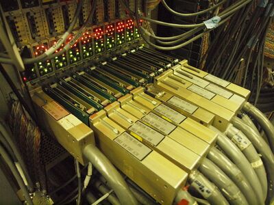
Large 50-conductor grey cables ran between the Slope Box on each detector to the Pickoff cards in the VXI crates of the old system. The VXI Pickoff Card received the single-ended signals for the Ge Center, Ge Sides, and BGO segments from the Slope Box. The VXI pickoff converted them to differential signal format before sending them to the digitizer. Signals had to be sent to the shack to be converted and conditioned in the previous system.
The previous design and layout of the pickoff card was dominated by the mechanics of having to be plugged in as an “inline” extension to the cable plant of the cards. The design used a “pass-through” motherboard with male and female connectors allowing the power, monitoring and control signals of the complex cable to pass unhindered, while bringing out the detector signals on headers. The actual “pickoff” card plugged into these headers to gain access to the analog signals to develop the differential analog signals used by the digitizers. The VXI pickoff card sufficed for the majority of Gammasphere experiments because only the GeCenter and BGOSum were used.
VXI Pickoff Card Features
- Three gain range options (jumper selectable from the bottom of the pickoff card) for the Ge Center: 2, 5, 10 MeV
- There was a fixed Preamp Reset Clamp that drove the Ge Center back to baseline after a preamp reset. They sometimes had oscillation problems (ringing) that could hinder resolution.
- There was an analog output on the VXI board. This LEMO output was shaped similar to a NIM Spectroscopy Amplifier, and was NOT what gets sent to the digitizer.

