DAQ system
This is an image map. Click on a section of the picture to go to the page for that item.
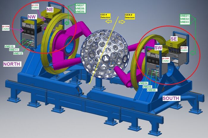
Gammasphere's DAQ system (data acquisition system) is now placed on relay racks by each side of its "hemispheres". Each of the racks for the DAQ consists of a power supply, a collector box, and a VME crate. The data acquisition system observes, interprets, and modifies data taken from Gammasphere and appropriately presents it to the user.
When Gammasphere collects data, single-ended signals are first collected from the slope box for the Ge Center, Ge Sides, and BGO segment. The signals are converted to differential signals by the SBX, and are then sent to the collector box so the signals can properly be routed to the digitizers. The digitizers process and output the desired information to the user based upon their data specifications. The DAQ system is an FPGA-based design that provides communication hub interfacing the preamp, power board, dongle and slope box to EPICS through serial interface. Analog signal paths are completely software controlled.
DAQ System Function
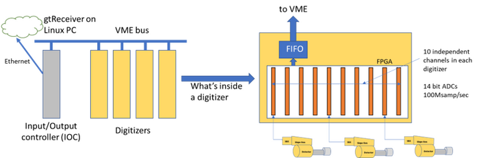
The DAQ system prior to upgrades consisted of VME crates, IOC Modules, Digitizers and Trigger Modules. There were two types of Digitizers (Master and Slave) and well as Trigger (Master and Router). In the current version of the upgraded Gammasphere DAQ system, some of the old hardware is still used, but in a different way. All channels in all digitizers run continuously. When discriminator logic marks leading edges of gamma-ray signals, energy sums, timing and other data are stored in a header identifying the event. If the event is selected for readout by the trigger system, the header and a programmable amount of waveform is transferred from the channel to the board-wide FIFO (first in, first out) data holder. The IOC scans the FIFOs to see if there is data to read out. If so, the IOC reads it out into buffers. A program called “gtReceiver” sends messages to each IOC when the receiver is ready for more data. The IOC then breaks apart buffers into UDP packets and sends them to gtReceiver. The gtReceiver program then routes the packets to files that may be organized by digitizer or by channel.
To view how this system is controlled, go to DGS Commander EDM Screens.
Go back to Digital Gammasphere Upgrade Project