DAQ system: Difference between revisions
No edit summary |
Nsensharma (talk | contribs) No edit summary |
||
| (19 intermediate revisions by 3 users not shown) | |||
| Line 1: | Line 1: | ||
'''''This is an image map. Click on a section of the picture to go to the page for that item.''''' | |||
<imagemap> | <imagemap> | ||
Image:GammasphereDAQupgrade.jpg|700px|center|thumb|Figure 1. DAQ System circled in red; one rack for each of the four "hemispheres" of Gammasphere | Image:GammasphereDAQupgrade.jpg|700px|center|thumb|Figure 1. DAQ System circled in red; one rack for each of the four "hemispheres" of Gammasphere | ||
| Line 11: | Line 12: | ||
poly 902 339 966 285 1034 321 976 356 [[DAQ Power Supply]] | poly 902 339 966 285 1034 321 976 356 [[DAQ Power Supply]] | ||
poly 1021 274 1081 225 1140 242 1089 293 [[DAQ Power Supply]] | poly 1021 274 1081 225 1140 242 1089 293 [[DAQ Power Supply]] | ||
poly 445 151 432 123 398 113 351 138 305 218 291 285 290 337 300 382 336 429 370 423 421 413 356 454 276 423 251 353 252 293 267 219 304 138 344 95 379 79 428 88 472 135 [[Liquid Nitrogen]] | |||
poly 838 557 809 506 804 446 808 384 828 320 865 258 911 222 960 212 1010 233 1021 293 991 288 969 251 950 241 935 239 901 264 876 300 860 331 846 378 839 428 839 470 847 516 850 532[[Liquid Nitrogen]] | |||
poly 502 374 499 305 519 251 564 207 615 184 660 181 713 195 759 233 783 277 796 329 788 382 764 427 710 470 648 483 587 471 533 431 [[Gammasphere|Gammasphere frame (without detectors in it)]] | |||
</imagemap> | |||
Gammasphere's DAQ system (data acquisition system) is now placed on relay racks by each side of its "hemispheres". Each of the racks for the DAQ consists of a [[DAQ Power Supply|power supply]], a [[Collector Box|collector box]], and a [[VME Crates|VME crate]]. The data acquisition system observes, interprets, and modifies data taken from [[Gammasphere]] and appropriately presents it to the user. | |||
The picture above provides an overall map to the naming conventions associated with the system. Cardinal directions are shown in '''purple''' text, process variable (EPICS) names are shown in '''green''' text and network IDs are shown in '''red''' text. There are multiple computers within the DAQ system: | |||
{| class="wikitable" | |||
|+These devices are used both by data acquisition and by control & monitoring | |||
|- | |||
! scope=col | Network name | |||
! scope=col | IP address | |||
! scope=col | Description | |||
|- | |||
| ioc01: || 192.168.203.141 || MVME5500 VME processor used for control and readout | |||
|- | |||
| ioc02: || 192.168.203.142 || MVME5500 VME processor used for control and readout | |||
|- | |||
| ioc03: || 192.168.203.143 || MVME5500 VME processor used for control and readout | |||
|- | |||
| ioc04: || 192.168.203.144 || MVME5500 VME processor used for control and readout | |||
|- | |||
| ioc05: || 192.168.203.145 || MVME5500 VME processor used for control and readout | |||
|- | |||
| ioc06: || 192.168.203.177 || MVME5500 VME processor used for control and readout | |||
|- | |||
| ioc07: || 192.168.203.178 || MVME5500 VME processor used for control and readout | |||
|- | |||
| ioc08: || 192.168.203.179 || MVME5500 VME processor used for control and readout | |||
|- | |||
| ioc09: || 192.168.203.180 || MVME5500 VME processor used for control and readout | |||
|- | |||
| ioc10: || 192.168.203.183 || MVME5500 VME processor used for control and readout | |||
|- | |||
| ioc11: || 192.168.203.181 || MVME5500 VME processor used for control and readout | |||
|- | |||
| ioc12: || 192.168.203.182 || MVME5500 VME processor used for control and readout | |||
|-} | |||
{| class="wikitable" | |||
|+These devices are used by control & monitoring only. | |||
|- | |||
! scope=col | Network name | |||
! scope=col | IP address | |||
! scope=col | Description | |||
|- | |||
| gs-cne || 192.168.203.88 || Raspberry Pi inside the North East Collector box | |||
|- | |||
| gs-cnw || 192.168.203.149 || Raspberry Pi inside the North West Collector box | |||
|- | |||
| gs-cse || 192.168.203.42 || Raspberry Pi inside the South East Collector box | |||
|- | |||
| gs-csw || 192.168.203.26 || Raspberry Pi inside the South West Collector box | |||
|-} | |||
{| class="wikitable" | |||
|+These devices are used by directly logging into them to control power to the VME crates, network switches and terminal servers. | |||
|- | |||
! scope=col | Network name | |||
! scope=col | IP address | |||
! scope=col | Description | |||
|- | |||
| gs-pdu-north || 192.168.203.224 || Power Distribution Unit for the North Hemisphere | |||
|- | |||
| gs-pdu_south || 192.168.203.225 || Power Distribution Unit for the North Hemisphere | |||
|-} | |||
{| class="wikitable" | |||
|+These devices are used by directly logging into them to connect to the console ports of IOC01 through IOC12. | |||
|- | |||
! scope=col | Network name | |||
! scope=col | IP address | |||
! scope=col | Description | |||
|- | |||
| gs-ts-north || 192.168.203.91 || Terminal server providing console port access for ioc07 through ioc12 | |||
|- | |||
| gs-ts_south || 192.168.203.186 || Terminal server providing console port access for ioc01 through ioc06 | |||
|-} | |||
{| class="wikitable" | |||
|+These devices are associated with the liquid nitrogen subsystem. | |||
|- | |||
! scope=col | Network name | |||
! scope=col | IP address | |||
! scope=col | Description | |||
|- | |||
| lnfill || 192.168.203.121 || Embedded VME processor that hosts the EPICS databases for valve status and valve control | |||
|- | |||
| ln2con || 192.168.203.148 || Linux computer that lnfill boots from | |||
|} | |||
When [[Gammasphere]] collects data, single-ended [[Detector Signals|signals]] are first collected from the slope box for the Ge Center, Ge Sides, and BGO segment. The signals are converted to differential signals by the [[The Slope Box Extension|SBX]], and are then sent to the collector box so the signals can properly be routed to the digitizers. The digitizers process and output the desired information to the user based upon their data specifications. The DAQ system is an FPGA-based design that provides communication hub interfacing the [[Preamplifier|preamp]], power board, dongle and slope box to EPICS through serial interface. Analog signal paths are completely software controlled. | When [[Gammasphere]] collects data, single-ended [[Detector Signals|signals]] are first collected from the slope box for the Ge Center, Ge Sides, and BGO segment. The signals are converted to differential signals by the [[The Slope Box Extension|SBX]], and are then sent to the collector box so the signals can properly be routed to the digitizers. The digitizers process and output the desired information to the user based upon their data specifications. The DAQ system is an FPGA-based design that provides communication hub interfacing the [[Preamplifier|preamp]], power board, dongle and slope box to EPICS through serial interface. Analog signal paths are completely software controlled. | ||
==DAQ System Function== | ==DAQ System Function== | ||
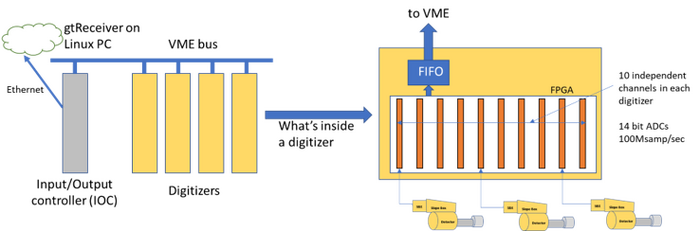
The DAQ system | The Gammasphere DAQ system consists of VME crates, IOC Modules, Digitizers and Trigger Modules. The original "analog" implementation of Gammasphere using the VXI modules used a charge-integrating ADC methodology and did not continuously digitize the data from the detectors. The Digital Gammasphere system (2010s) introduced the digitizers as a replacement for the charge-integrating ADC functions of the VXI modules and replaces the "analog" system's trigger by a new trigger system, requiring a redesign of the DAQ. The later "Gammasphere Upgrade" project (2019-2023) that resulted in the SBX, preamp and collector box hardware did not materially affect the DAQ but replaced all of the remaining control, monitoring and power distribution functions of the VXI system allowing removal of the VXI system and associated cable plant. | ||
Each digitizer in the system consists of 10 channels, but should be conceptualized as a pair of two ''sub-digitizers'' consisting of five channels each. There are two types of digitizers: master and slave. A pair of channels in a master digitizer receives signals from the Ge center and BGO sum from a single Gammasphere detector, while a channel-pair in the slave digitizer receives signals from the Ge side and BGO pattern. All channels in all digitizers run continuously. There are two types of digitizers (master and slave) as well as two types of triggers (master and router). | |||
When discriminator logic within the digitizer firmware marks edges of gamma-ray signals, energy sums, timing and other data are stored in a header identifying the event. If the event is selected for readout by the trigger system, the header and a programmable amount of waveform is transferred from the channel to the board-wide FIFO (first in, first out) data holder. Similarly the trigger modules have FIFO buffers that store information each time a trigger acceptance message is issued to the digitizers. The IOC scans the FIFOs of all modules to see if there is data to read out through a series of programs named inLoop, outLoop and MiniSender. If data is available, the inLoop program reads it and stores the data read into memory buffers. Program outLoop verifies the integrity of the buffers and then hands control of the buffers to the MiniSender program. A separate program running on a different computer called “gtReceiver” sends messages to each IOC's MiniSender program when it is capable of receiving data. The MiniSender program of each IOC, in response to requests from gtReceiver, then breaks apart buffers into UDP packets and sends them to gtReceiver. The gtReceiver program then stores the data received to files that may be organized by digitizer or by channel. | |||
<imagemap> | <imagemap> | ||
Image:DAQSystem.png|center|thumb|700px|Figure 2. Diagram of the DAQ system process. | Image:DAQSystem.png|center|thumb|700px|Figure 2. Diagram of the DAQ system process. | ||
| Line 31: | Line 120: | ||
</imagemap> | </imagemap> | ||
''To view how this system is controlled, go to [[DGS Commander EDM Screens]].'' | |||
''Go back to [[Digital Gammasphere Upgrade Project]]'' | ''Go back to [[Digital Gammasphere Upgrade Project]]'' | ||
Latest revision as of 17:21, July 31, 2023
This is an image map. Click on a section of the picture to go to the page for that item.
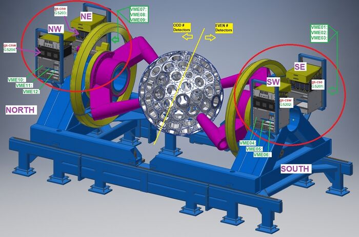
Gammasphere's DAQ system (data acquisition system) is now placed on relay racks by each side of its "hemispheres". Each of the racks for the DAQ consists of a power supply, a collector box, and a VME crate. The data acquisition system observes, interprets, and modifies data taken from Gammasphere and appropriately presents it to the user.
The picture above provides an overall map to the naming conventions associated with the system. Cardinal directions are shown in purple text, process variable (EPICS) names are shown in green text and network IDs are shown in red text. There are multiple computers within the DAQ system:
| Network name | IP address | Description |
|---|---|---|
| ioc01: | 192.168.203.141 | MVME5500 VME processor used for control and readout |
| ioc02: | 192.168.203.142 | MVME5500 VME processor used for control and readout |
| ioc03: | 192.168.203.143 | MVME5500 VME processor used for control and readout |
| ioc04: | 192.168.203.144 | MVME5500 VME processor used for control and readout |
| ioc05: | 192.168.203.145 | MVME5500 VME processor used for control and readout |
| ioc06: | 192.168.203.177 | MVME5500 VME processor used for control and readout |
| ioc07: | 192.168.203.178 | MVME5500 VME processor used for control and readout |
| ioc08: | 192.168.203.179 | MVME5500 VME processor used for control and readout |
| ioc09: | 192.168.203.180 | MVME5500 VME processor used for control and readout |
| ioc10: | 192.168.203.183 | MVME5500 VME processor used for control and readout |
| ioc11: | 192.168.203.181 | MVME5500 VME processor used for control and readout |
| ioc12: | 192.168.203.182 | MVME5500 VME processor used for control and readout |
| Network name | IP address | Description |
|---|---|---|
| gs-cne | 192.168.203.88 | Raspberry Pi inside the North East Collector box |
| gs-cnw | 192.168.203.149 | Raspberry Pi inside the North West Collector box |
| gs-cse | 192.168.203.42 | Raspberry Pi inside the South East Collector box |
| gs-csw | 192.168.203.26 | Raspberry Pi inside the South West Collector box |
| Network name | IP address | Description |
|---|---|---|
| gs-pdu-north | 192.168.203.224 | Power Distribution Unit for the North Hemisphere |
| gs-pdu_south | 192.168.203.225 | Power Distribution Unit for the North Hemisphere |
| Network name | IP address | Description |
|---|---|---|
| gs-ts-north | 192.168.203.91 | Terminal server providing console port access for ioc07 through ioc12 |
| gs-ts_south | 192.168.203.186 | Terminal server providing console port access for ioc01 through ioc06 |
| Network name | IP address | Description |
|---|---|---|
| lnfill | 192.168.203.121 | Embedded VME processor that hosts the EPICS databases for valve status and valve control |
| ln2con | 192.168.203.148 | Linux computer that lnfill boots from |
When Gammasphere collects data, single-ended signals are first collected from the slope box for the Ge Center, Ge Sides, and BGO segment. The signals are converted to differential signals by the SBX, and are then sent to the collector box so the signals can properly be routed to the digitizers. The digitizers process and output the desired information to the user based upon their data specifications. The DAQ system is an FPGA-based design that provides communication hub interfacing the preamp, power board, dongle and slope box to EPICS through serial interface. Analog signal paths are completely software controlled.
DAQ System Function
The Gammasphere DAQ system consists of VME crates, IOC Modules, Digitizers and Trigger Modules. The original "analog" implementation of Gammasphere using the VXI modules used a charge-integrating ADC methodology and did not continuously digitize the data from the detectors. The Digital Gammasphere system (2010s) introduced the digitizers as a replacement for the charge-integrating ADC functions of the VXI modules and replaces the "analog" system's trigger by a new trigger system, requiring a redesign of the DAQ. The later "Gammasphere Upgrade" project (2019-2023) that resulted in the SBX, preamp and collector box hardware did not materially affect the DAQ but replaced all of the remaining control, monitoring and power distribution functions of the VXI system allowing removal of the VXI system and associated cable plant.
Each digitizer in the system consists of 10 channels, but should be conceptualized as a pair of two sub-digitizers consisting of five channels each. There are two types of digitizers: master and slave. A pair of channels in a master digitizer receives signals from the Ge center and BGO sum from a single Gammasphere detector, while a channel-pair in the slave digitizer receives signals from the Ge side and BGO pattern. All channels in all digitizers run continuously. There are two types of digitizers (master and slave) as well as two types of triggers (master and router).
When discriminator logic within the digitizer firmware marks edges of gamma-ray signals, energy sums, timing and other data are stored in a header identifying the event. If the event is selected for readout by the trigger system, the header and a programmable amount of waveform is transferred from the channel to the board-wide FIFO (first in, first out) data holder. Similarly the trigger modules have FIFO buffers that store information each time a trigger acceptance message is issued to the digitizers. The IOC scans the FIFOs of all modules to see if there is data to read out through a series of programs named inLoop, outLoop and MiniSender. If data is available, the inLoop program reads it and stores the data read into memory buffers. Program outLoop verifies the integrity of the buffers and then hands control of the buffers to the MiniSender program. A separate program running on a different computer called “gtReceiver” sends messages to each IOC's MiniSender program when it is capable of receiving data. The MiniSender program of each IOC, in response to requests from gtReceiver, then breaks apart buffers into UDP packets and sends them to gtReceiver. The gtReceiver program then stores the data received to files that may be organized by digitizer or by channel.
To view how this system is controlled, go to DGS Commander EDM Screens.
Go back to Digital Gammasphere Upgrade Project