Digitizer Channel Design Overview: Difference between revisions
Created page with "== Channel Design Overview == The 10 channels of the firmware are implemented as continuously running data pipelines. Data enters the pipeline every tick of the clock from th..." |
No edit summary |
||
| Line 21: | Line 21: | ||
''Go back to [[ANL Digitizer Firmware for Advanced Users]]'' | ''Go back to [[ANL Digitizer Firmware for Advanced Users]]'' | ||
''Go back to [[Digital Gammasphere | ''Go back to [[Digital Gammasphere Upgrade Project]]'' | ||
Latest revision as of 14:22, October 5, 2021
Channel Design Overview
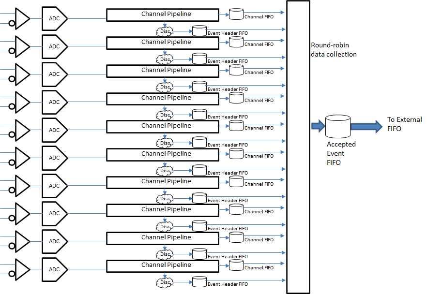
The 10 channels of the firmware are implemented as continuously running data pipelines. Data enters the pipeline every tick of the clock from the ADC, proceeds through the pipeline and eventually falls off the back end. If conditions are satisfied data samples at the back end are copied into a buffer known as the Channel FIFO.
In the middle of the pipeline multiple delay buffers with accumulators provide running sums of the data spanning programmable ranges of time.
Other delay buffers in the pipeline provide delays for calculation of discriminator functions. When a discriminator hit occurs, various time values and data sums are stored as a header. Headers are stored in an Event Header FIFO that holds the headers so long as the associated waveform data is still in pipeline.

Channel Interactions
When an event is selected for readout, the header from the Event Header FIFO is combined with the matching set of ADC data samples from the Channel FIFO, and this package of data is sent to the board-wide Accepted Event FIFO that services all 10 channels. The Accepted Event FIFO is drained by a state machine that copies the data to the FIFO memory external to the FPGA unless the external FIFO cannot be written to because it is too full; in that case the data is lost and counted as a dropped event. Because there are 10 Channel FIFOs that fill simultaneously from all 10 channels but only one Accepted Event FIFO, large event sizes combined with sufficient rate may result in dropped events because the channels block each other from access to the Accepted Event FIFO.
Channel Pipeline Structure
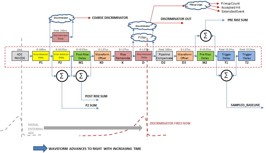
The pipeline structure found in every channel is shown as Figure 3. The signal enters at the left and propagates to the right with time, backwards of a traditional oscilloscope image. When the edge of the signal reaches the middle, where the discriminator logic lies, the discriminator fires, capturing all the sum values shown plus timestamp and status information. This is all read out in the header of the data as explained in the next section.
Note the discriminator in the middle of the design across buffer ‘d’, and the coarse discriminator placed well earlier in the pipeline.

Go back to ANL Digitizer Firmware for Advanced Users
Go back to Digital Gammasphere Upgrade Project