How trigger throttling works
Design and operation of the trigger throttling function
This is a draft document and is a work in progress.
Throttling is a term used to specifically describe the temporary cessation of trigger acceptance messages from the trigger system to the digitizer modules. The reader is reminded that the trigger system receives various inputs from the digitizers and from external sources, and from those the trigger issues Trigger Accept messages that cause events within a given timestamp range relative to the timestamp at which the trigger condition was met. Delay in the issuance and reception of the trigger accept message is, to first order, immaterial as the match comparison is between the timestamp of the discriminator firing and the timestamp contained within the Trigger Accept message, not the timestamp at which the message is sent or arrived. As events flow through the digitizer, a queue of Pending Events is formed within the firmware for each channel. When run in the Internal mode, every Pending Event is read out and passes unscathed to the board-wide FIFO of the digitizer. When run in the "TTCL" (or triggered mode), only those Pending Events that have been marked by timestamp comparison against timestamps in the Trigger Accept messages are passed to the board-wide FIFO, and all other Pending Events are discarded.
In general trigger messages can be generated at rates up 500kHz, with trigger algorithms independently capable of handling bursts of triggers at rates in excess of 5MHz. Similarly, each channel of a digitizer module can fire at rates >500kHz (depending upon parameters) but limitations in both the internal queueing of per-channel information into the digitizer module's FIFO buffer and also the rate of FIFO readout over the VME bus can result in conditions where some channel(s) of some digitizer(s) would benefit by temporarily stopping the Trigger Accept messages to avoid buffer overflow or lost events.
Throttling is distinct from and complementary to simple pre-scaling of the trigger rate. Throttling is based on signals sent from the digitizers themselves to the trigger and thus forms a true closed-loop feedback system to modulate trigger rates.
Block diagrams
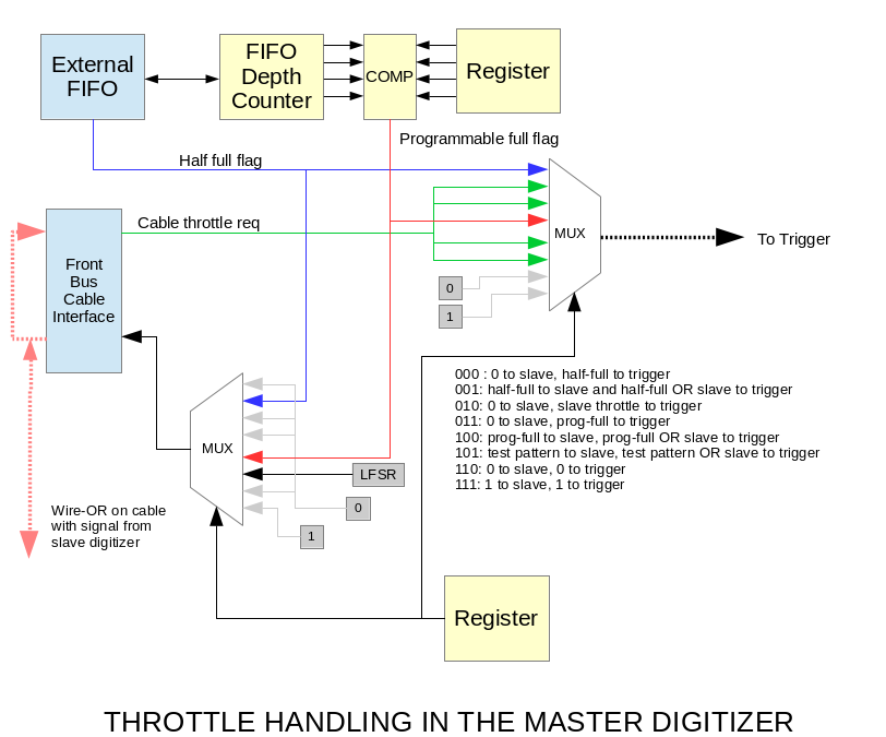
The ANL digitizer firmware comes in two varieties, master and slave. Only master digitizers are used in DFMA and Digios, but DGS has both masters and slaves. The master digitizer is the one that connects to the trigger system and can assert a throttle request. The figure below summarizes the options available within the master digitizer for generating throttle requests. Let us for the moment consider systems that have only master digitizers. In these systems there is no front panel cable and thus the throttle source selections that use the cable may be generally ignored. This reduces the drawing below to just two options, mode 000 (send half-full as throttle) and mode 011 (send prog-full as throttle).
In GRETINA, only the half-full flag was available as the throttle output. The Prog-full is specific to ANL versions of digitizer firmware.
Readout software interaction with throttle
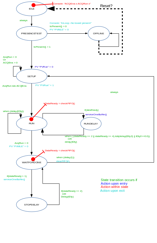
It is most important to consider how the readout software running in the VME processor may influence the proper choice of throttle source. For every digitizer in a given VME crate there is one instance of a state machine thread that polls the digitizer at regular intervals to determine if there is "enough" data in the digitizer to warrant readout. This design choice - what constitutes "enough" - is a complex function. From the VME side, maximum bandwidth is achieved by having the processor read the biggest blocks of data possible, and minimizing the rate at which modules are polled for status. This is because single VME read/write transactions (such as polling) are very slow in comparison to reads in a block transfer (DMA) operation. By the same token, the time it takes to set up the DMA transfer and the time it takes to end the DMA transfer are fixed duration time penalties that are mitigated by increasing the size of the block transfer to run at maximum bandwidth for longer periods.
However, with multiple competing state machine threads for multiple digitizers, using the longest possible block transfers for each runs the risk of a digitizer's FIFO overflowing while some other digitizer is being read out. A second concern has to do with the event building software behind the readout. If the event rates across digitizers within a crate is widely variant, a system where readout waits for a certain threshold of data to be available before readout ensues will mean that the data from the less active digitizer will have much longer latency from acquisition to readout because the FIFO fills slowly. This can cause event building problems because such latency will force the event builder to manage far larger event sets than if rates were more balanced across the system, especially if the IOC is attempting to sort events by timestamps across its set of digitizers before sending the events to the event builder.
In an attempt to strike a balance, the state machine used for each digitizer has been modified to include a time-out term to force a readout in any given state machine if no readout has occurred for a given amount of time.
Breakdown of solution by module type
Digitizers
Correct selection of parameters within the digitizer is paramount for obtaining maximum throughput. Each of the 10 channels of a digitizer is an independent pipeline that constantly runs at the full sampling speed (100MHz). This full-speed operation is maintained throughout the pipeline and into the buffer that holds the Pending Events. Only at the last moment, when data from Accepted Events is read out of the pipeline and into the FIFO system, does down-sampling occur. While down-sampling will reduce data volume as written to the board-wide FIFO, the entire full-speed dataset is continuously processed; thus down-sampling only helps from a volume standpoint and cannot change the rate at which raw pipeline data is processed.
The FIFO system of the digitizer firmware has three stages.
- On a channel-by-channel basis each pipeline's Accepted Events are copied into a buffer called the Accepted Event FIFO. The Accepted Event FIFO is 2048 sixteen-bit words deep. Every event has a header that is 28 sixteen-bit words long; thus the number of events that can be simultaneously held in the Accepted Event FIFO is extremely dependent upon the amount of waveform information stored per event. Thankfully, down-sampling does help here, but if the Accepted Event FIFO backs up to the point where the next Accepted Event won't fit in the Accepted Event FIFO at the time the Accepted Event becomes ready, the event must be dropped and data is lost. A per-channel Dropped Event Counter monitors this activity.
- On a board-wide basis, a state machine scans the 10 Accepted Event FIFOs in round-robin channel order, copying events one at a time from each of the 10 Accepted Event FIFOs into a single Collected Event FIFO. The efficiency of this process is obviously dependent upon event size, but is also quite dependent upon the event rate present in each channel. Because the state machine scans in strict channel order with no preference, significant imbalance in the event rate across channels of an individual digitizer may force some channels to drop events because the Accepted Event FIFO for that channel doesn't get emptied rapidly enough.
- Also on a board-wide basis, another state machine is tasked with copying events from the Collected Event FIFO to the larger Board-Wide FIFO implemented outside the FPGA of the digitizer. The FIFO chip itself has only a half-full flag but the ANL digitizer firmware implements a counter-based piece of logic that can assert a "programmable full" at any 1/16th of the FIFO depth as selected by the user.
In the cabling scheme as originally developed for GRETINA, there is one signal throttle request that connects from each digitizer module to the trigger system. The traditional method of implementing a throttle request from digitizer to router has been to take the FIFO programmable-full flag and use that directly. In this architecture, if any digitizer's board-wide FIFO gets too full, a throttle request is asserted and the trigger simply ORs all the throttle requests together such that triggers are vetoed if any digitizer gets too full. This is not unreasonable for systems with a very small number of digitizers, but as the number of sources of throttle request increases the OR of all throttle requests quickly approaches the state of ON all the time, so no data flows. Thus some kind of time-based filtering of the throttle request signals from large numbers of digitizer channels is required.
Router Triggers
The task of time-filtering the throttle request signal from each digitizer falls to the router trigger boards. The router implements a set of eight time filters (one per digitizer), driven by the separate throttle request line in the cable from digitizer to router. This information is not sent over the SERDES link.
The time filter consists of a state machine that rejects any throttle requests that are too short in duration so that the master trigger does not 'see' transient throttle requests. In other words, any given throttle request isn't considered "real" unless it has persisted continuously for some number of clock ticks. When a throttle request has passed the "too short" filter, the signal then enters a programmable one-shot that enforces a minimum assertion time to the master trigger. Generally the "too short" time is set in milliseconds and the minimum assertion time is set in tens of nanoseconds; for example, 50usec and 100ns are a good starting point.
Within the router trigger the 8 filtered throttle requests are themselves ORed together and the resultant single bit is sent on the SERDES link to the master trigger.
Master Trigger
The master trigger collects the OR of the filtered throttle requests from each Router to create a single system-wide throttle request. This may then be enabled by the user as a source of trigger veto.
Other Devices
Relevant data flows
Trigger Timing and Command Link from master to routers
Trigger Timing and Command Link from router to digitizer
Data Link from digitizer to router
Data Link from routers to master
Major firmware sections in use by module type
Master Trigger
Router Triggers
Digitizers
Other Devices
- Specific links to the formal documentation for further details.
- Explicit new drawings specific to the application that are explained with detailed text to show not only how it works but also how to set it up

