Master
Jump to navigation
Jump to search
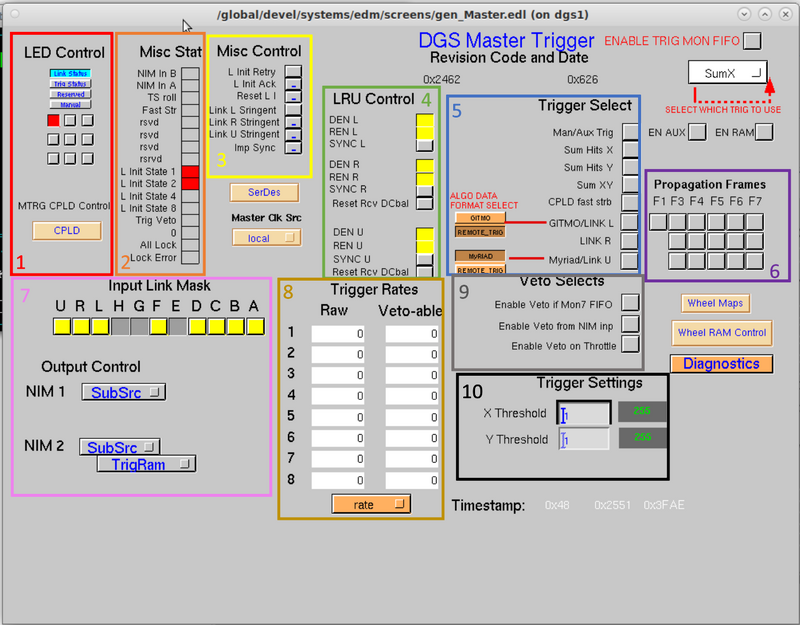
This screen gives controls and monitoring for the Master trigger of the DAQ system. The master trigger implements 11 bi-directional communications links. Each link (named A,B,C,D,E,F,G,H,L,R,U) is capable of transmitting data at 1Gbit/sec while simultaneously receiving data at 1Gbit/sec. The system connectivity is hierarchical. The master trigger communicates with router trigger modules within its detector system via links A-H, a master trigger module of another detector system via either link L or link R, and a MyRIAD module of another detector system via link U. The master trigger continuously transmits information to every module.
- Section 1 of the screen inside red box is for LED Control.
- Section 2 of the screen inside orange box is for miscellaneous statistics. It is an indicator, which shows the user
- Section 3 of the screen inside yellow box contain miscellaneous controls.
- Section 4 of the screen inside green box is for LRU Control. It handles the "L", "R", and "U" links for communication with other systems.
- Section 5 of the screen inside blue box is for trigger selections.
- Section 6 of the screen inside purple box is for propagation frames.
- Section 7 of the screen inside pink box is for input link masks and output control. Trigger modules have a mix of front panel I/O connections to allow users to attach external cabling. The most heavily used of these are the NIM I/O connections. NIM stands for Nuclear Instrumentation module. There are two NIM outputs and two NIM inputs. The two NIM outputs have many different choices of what signals are driven out, controlled by the Output Control selections. The two NIM inputs have variant function dependent upon the needs of the user. NIM input 1 can be used as an Auxiliary trigger input signal, that may be used to cause a trigger accept message. NIM input 2 can be used either as a trigger Veto input, that may be used to veto issuance of trigger accept messages or may alternately be used as the RF Clock input for the master trigger’s time-to-digital converter (TDC) function.
- Section 8 of the screen inside gold box is for trigger rates. They show the raw data the trigger recieves, and, based on user input, the amount of veto-able data.
- Section 9 of the screen inside gray box is for veto selects.
- Section 10 of the screen inside black box is for trigger settings.

Go back to Trigger Options