Master: Difference between revisions
Jump to navigation
Jump to search

No edit summary |
No edit summary |
||
| Line 3: | Line 3: | ||
*Section 2 of the screen inside '''orange''' box is for miscellaneous statistics. | *Section 2 of the screen inside '''orange''' box is for miscellaneous statistics. | ||
*Section 3 of the screen inside '''yellow''' box contain miscellaneous controls. | *Section 3 of the screen inside '''yellow''' box contain miscellaneous controls. | ||
*Section 4 of the screen inside '''green''' box is for LRU Control. | *Section 4 of the screen inside '''green''' box is for LRU Control. It handles the "L", "R", and "U" links for communication with other systems. | ||
*Section 5 of the screen inside '''blue''' box is for trigger selections. | *Section 5 of the screen inside '''blue''' box is for trigger selections. | ||
*Section 6 of the screen inside '''purple''' box is for propgation frames. | *Section 6 of the screen inside '''purple''' box is for propgation frames. | ||
Revision as of 17:17, March 21, 2023
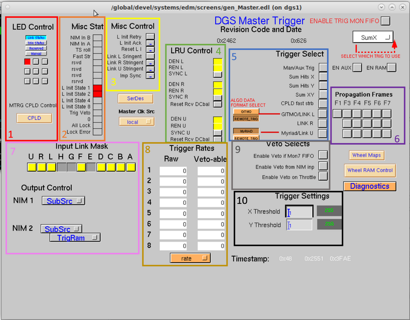
This screen gives controls and monitoring for the Master trigger of the DAQ system. The master trigger implements 11 bi-directional communications links. Each link (named A,B,C,D,E,F,G,H,L,R,U) is capable of transmitting data at 1Gbit/sec while simultaneously receiving data at 1Gbit/sec. The system connectivity is hierarchical. The master trigger communicates with router trigger modules within its detector system via links A-H, a master trigger module of another detector system via either link L or link R, and a MyRIAD module of another detector system via link U. The master trigger continuously transmits information to every module.
- Section 1 of the screen inside red box is for LED Control.
- Section 2 of the screen inside orange box is for miscellaneous statistics.
- Section 3 of the screen inside yellow box contain miscellaneous controls.
- Section 4 of the screen inside green box is for LRU Control. It handles the "L", "R", and "U" links for communication with other systems.
- Section 5 of the screen inside blue box is for trigger selections.
- Section 6 of the screen inside purple box is for propgation frames.
- Section 7 of the screen inside pink box is for input link masks.
- Section 8 of the screen inside gold box is for trigger rates.
- Section 9 of the screen inside gray box is for veto selects.
- Section 10 of the screen inside black box is for trigger settings.

Go back to Trigger Options