Master: Difference between revisions
Jump to navigation
Jump to search

No edit summary |
No edit summary |
||
| Line 2: | Line 2: | ||
<imagemap> | <imagemap> | ||
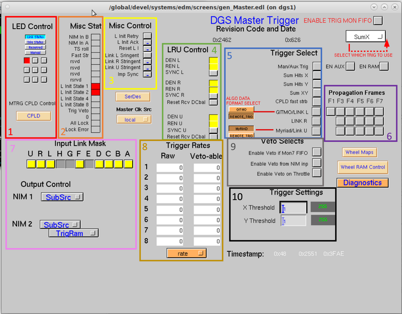
Image:MasterTriggerFigure.png|800px|center | Image:MasterTriggerFigure.png|800px|center | ||
rect | rect 56 377 171 406 [[Master Trigger CPLD Screen]] | ||
rect | rect 390 311 504 341 [[SerDes Screen]] | ||
rect | rect 1152 499 1268 528 [[Master Trigger Wheel Maps Options]] | ||
rect | rect 1137 542 1304 587 [[Wheel RAM Control Screen]] | ||
rect | rect 1133 602 1305 628 [[Master Trigger Diagnostics Screen]] | ||
</imagemap> | </imagemap> | ||
''Go back to [[Trigger Options]]'' | ''Go back to [[Trigger Options]]'' | ||
Revision as of 17:08, March 21, 2023
This screen gives controls and monitoring for the Master trigger of the DAQ system. The master trigger implements 11 bi-directional communications links. Each link (named A,B,C,D,E,F,G,H,L,R,U) is capable of transmitting data at 1Gbit/sec while simultaneously receiving data at 1Gbit/sec. The system connectivity is hierarchical. The master trigger communicates with router trigger modules within its detector system via links A-H, a master trigger module of another detector system via either link L or link R, and a MyRIAD module of another detector system via link U. The master trigger continuously transmits information to every module.

Go back to Trigger Options