Master
This screen gives controls and monitoring for the Master trigger of the DAQ system. The master trigger implements 11 bi-directional communications links. Each link (named A,B,C,D,E,F,G,H,L,R,U) is capable of transmitting data at 1Gbit/sec while simultaneously receiving data at 1Gbit/sec. The system connectivity is hierarchical. The master trigger communicates with router trigger modules within its detector system via links A-H, a master trigger module of another detector system via either link L or link R, and a MyRIAD module of another detector system via link U. The master trigger continuously transmits information to every module.
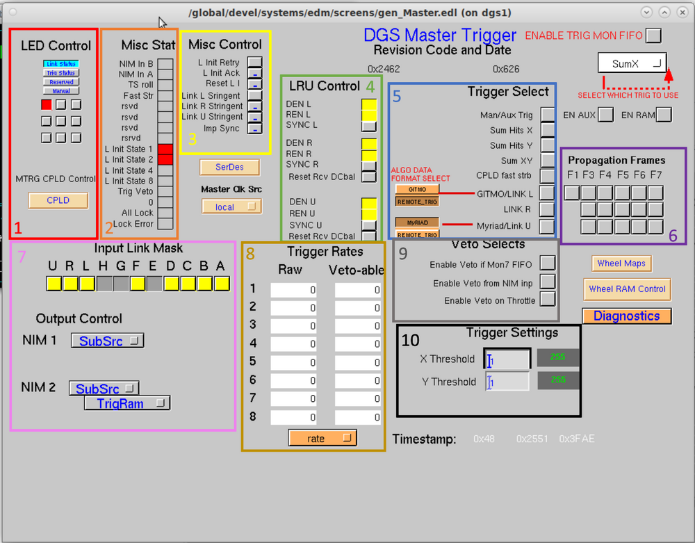
- Section 1 of the screen inside the red box is for LED Control.
- Section 2 of the screen inside the orange box is for miscellaneous statistics. It is an indicator, which shows the user the activity with the module or function listed next to it.
- Section 3 of the screen inside the yellow box contain miscellaneous controls.
- Section 4 of the screen inside the green box is for LRU Control. It handles the "L", "R", and "U" links for communication with other systems. "LRU" refers to the three communication links that can be paired with other systems, and the control section is for controlling their function. The DEN, REN, and SYNC controls are in section 4 to set the synchronization pattern.
- Section 5 of the screen inside the blue box is for trigger selections. Trigger Accept messages tell the digitizers what subset of data to make available for readout. In the Trigger Select section, the user may select different trigger algorithms to be active or inactive for the purpose of making these trigger accept messages. Different trigger algorithms are associated with different data collected both from the local system and the external systems.
- Section 6 of the screen inside the purple box is for propagation frames. Master triggers may be connected to other Master Triggers via a 1Gbit/sec cable, allowing them to broadcast their TTCL link (clock, timestamp, trigger accepts, etc.) to each other. When connected this way the receiving master trigger has registers known as the propagation control registers that allow them to select what parts of the other trigger’s TTCL they will listen to. If the receiving master is receiving information over link L, then the F1 bit in the link L propagation control register allows this master trigger to use the clock of the other master trigger as it’s clock just like is done within a local system, causing two disparate systems to be synchronized.If other propagation control bits are set then the related subclass of trigger accept messages from the remote master trigger may be propagated into the local system as additional trigger accepts beyond those calculated locally.
- Section 7 of the screen inside the pink box is for input link masks and output control. Trigger modules have a mix of front panel I/O connections to allow users to attach external cabling. The most heavily used of these are the NIM I/O connections. NIM stands for Nuclear Instrumentation module. There are two NIM outputs and two NIM inputs. The two NIM outputs have many different choices of what signals are driven out, controlled by the Output Control selections. The two NIM inputs have variant function dependent upon the needs of the user. NIM input 1 can be used as an Auxiliary trigger input signal, that may be used to cause a trigger accept message. NIM input 2 can be used either as a trigger Veto input, that may be used to veto issuance of trigger accept messages or may alternately be used as the RF Clock input for the master trigger’s time-to-digital converter (TDC) function.
- Section 8 of the screen inside the gold box is for trigger rates. They show the raw data the trigger recieves, and, based on user input, the amount of veto-able data.
- Section 9 of the screen inside the gray box is for veto selects. The given options allow a user to enable vetoing in certain cases or areas of data acquisition.
- Section 10 of the screen inside the black box is for trigger settings.
This is a clickable image. Click on the buttons in the picture to go to the page for that item.

Go back to Trigger Options