Linking Systems Together
Linking Multiple Systems Together
The trigger logic implemented for the various DAQ systems and the hardware design of the trigger module allows for the possibility to link multiple systems together. This allows both clock synchronization and trigger sharing to occur. A number of rules must be obeyed, so read carefully.
Physical Connectivity and basic firmware controls
Just plugging in a cable or a fiber is not sufficient to make anything work.
- Every link (A,B,C,D,E,F,G,H,L,R,U) of a trigger module has an Input Link Mask bit associated with it.
- If a link is masked, the trigger module will not use any data coming in on that link.
- If a link is masked, the trigger module won't send the data you want it to send, either.
- In the GUI screens, the color GRAY means "link is masked" and the color YELLOW means "link is in use/valid".
- While the Input Link Mask is a firmware control, there is also a level of hardware control associated with the cable driver/receiver chips.
- There are controls named DEN (Driver ENable), REN (Receiver ENable) and SYNC that tell the cable driver/receiver chips to operate.
- For cross-triggering operation, DEN and REN should be ON and SYNC should be OFF.
- There are controls named DEN (Driver ENable), REN (Receiver ENable) and SYNC that tell the cable driver/receiver chips to operate.
- System linkup scripts will usually leave the SYNC bit for links L, R, U in the ON state, so to link systems the SYNC should be turned OFF.
Clock Sharing
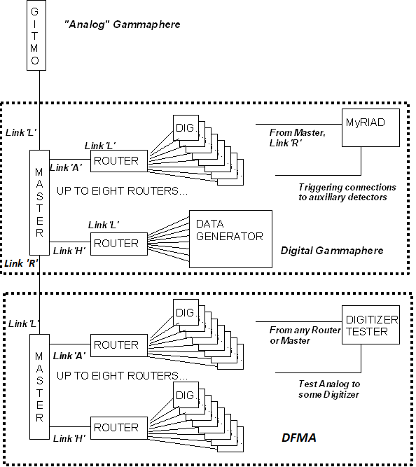
The basic method of clock sharing that most users are familiar with is that the master trigger sends clock to the routers, and the routers re-distribute that clock to the digitizers. Many users also understand that this tree of clock distribution has been extended to include Digital Gammasphere (DGS) sending the clock to DFMA, as shown here.
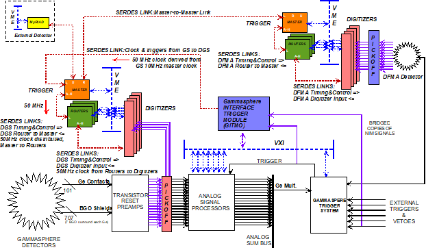
Those that have been involved from the beginning will recall that the DGS master trigger could also be connected to 'Analog' Gammasphere using the GITMO module - and use the clock from 'Analog' Gammasphere. Those that have been involved with hosting external detectors such as CHICO, Microball, ORRUBA, etc. also understand that there is clock sharing associated with the MyRIAD module. A more full picture of this clock distribution hierarchy is shown here.
The rules of the game as currently understood by users
So people know that you can hook a MyRIAD to DGS, and you can hook DFMA to DGS, and that with appropriate software incantations the clock and timestamp can be distributed from DGS to the other two systems. That is correct, and that is true, but it is not the whole and complete truth of how the firmware works.
How clock sharing REALLY works
How the clock sharing works in full detail is as follows.
- Any master trigger can be declared as the "timing monarch" that is the source of the clock.
- Which master trigger is the "timing monarch" is defined solely by cabling.
- If a master trigger has a cable connected to it's link L then that master trigger can be told to be subservient to whatever is on the other end of the link L cable.
- The hierarchy is defined by what cables plug into link L of what boards.
- This is why all the master-to-router cables go from any link of the master always to link L of the router.
- There is a limit as to how far the hierarchy can descend.
- Each time the clock is sent out of a board and received by another, clock jitter accumulates with each 'hop'.
- In the DGS-DFMA setup that people are used to, there are six 'hops' to get a trigger from DFMA back to DGS when DGS is the clock source :
- DGS to DFMA master -> DFMA master-router -> DFMA router-digitizer -> DFMA digitizer-router -> DFMA router-master -> DFMA master to DGS
- Measurements show that the accumulated jitter per 'hop' is about 35ps.
- So in the DGS-DFMA setup there would be a total accumulated jitter of (6*35), or 360ps.
- The serial data stream is 1Gbps, or 1ns (1000ps) per bit.
- If the ratio of the accumulated jitter divided by the bit period is greater than 50%, the link WILL HAVE BIT ERRORS.
- Thus the number of 'hops' in the current system is at a maximum and hanging a 3rd system behind DFMA will not work.
Any master trigger starts up using its own internal clock. Then, by writing a bit to a register, a master trigger agrees to use the clock that comes in on link L. The firmware has an automatic fallback provision that will cause any master trigger to fall back to using the internal clock irrespective of the software selection if there is no LOCK indication from the SERDES chip of link L. Thus it is necessary to establish the SERDES link between two master triggers and verify that link L is locked BEFORE telling the "subservient" master trigger to use the clock from link L.
Understanding Link usage
Each master trigger board has three "special" SERDES links named "L", "R" and "U". Originally this was meant to be read as "Left", "Right" and "Up" for drawing complicated link connections, but the convention of direction was abandoned unused. These three links are "special" in the sense that they are intended to be used as system interconnect links as opposed to the internal connections of links A through H. More precisely, what this means is that the data formats that these links send and receive are slightly different than the data format used to connect with routers. Each of these three links has a unique purpose and unique characteristics.
- Link L is unique in that it alone can receive a clock from an external source that can be used in place of the board's internal clock.
- Link L can receive two different data formats, either the GITMO format or the format from another master trigger.
- Link R is intended to receive data from another master trigger.
- Link U is historically used with the MyRIAD module to receive trigger information from an external detector.
- Link U can be programmed to receive data from another master trigger.
General recipe for success
- Run local scripts for each system to link everybody up within each system individually.
- Adjust Input Link Mask bits on links L, R, U of cross-connected systems so that the triggers send nice data to each other.
- Adjust Sync bits on links L, R, U of cross-connected systems so that triggers send nice data to each other.
- Turn on the F1 propagation bit of the systems that are subservient to the designated timing monarch.
- Set the Clock Source of the systems that are subservient to the designated timing monarch to 'link'.
- this will cause some digitizers or routers to drop the link or have 'lost lock' errors. Reset errors and/or links as needed to re-link routers to master and then to re-link digitizers to routers as needed.
- Turn on the Imperative Sync of the timing monarch. Verify that subservient systems respond at all levels of boards (master, routers, digitizers).
- As desired, Turn on F3 (and, if needed, F4, F5, F6, etc.) Propagation Control bits in systems subservient to the timing monarch to tell the systems to listen to and process triggers sent by the timing monarch.
- As desired, Turn on F3 (and, if needed, F4, F5, F6, etc.) Propagation Control bits in the timing monarch to tell the timing monarch to listen to and process triggers sent by the subservient systems.
- the purpose of the Propagation Control bits is to select which triggers from other systems are to be listened to by the system with the Propagation Control bits.
- The F4/5/6/etc. bits are there to allow a system to listen to multiple trigger messages from multiple algorithms if the trigger setup is that complex.
- the purpose of the Propagation Control bits is to select which triggers from other systems are to be listened to by the system with the Propagation Control bits.
- Send test triggers and see that they occur in the other systems.
- Learn how to use the Manual Trigger bit in the Pulsed Control register and the Trig RAM logic to generate triggers at will without any beam and without any digitizers.
Expert diagnosis tricks
There is a script that allows experts to look at the raw data being received on link L, R or U of any master trigger. Experts know what the appropriate data pattern looks like.
- data pattern of constant value of 0x00FF means that the sending device still has the hardware SYNC control on.
- data pattern of constant value of 0xFF00 means that the sending device still has the Input Link Mask bit in the gray state.
The concept of Propagation Control
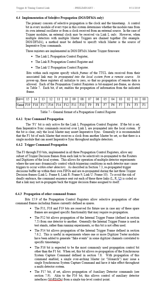
Every master trigger is the master of its own detector. However, each master trigger that is receiving data from another master trigger from the SERDES links (L, R or U) can selectively propagate information received from another master trigger into itself. There is a Propagation Control register associated with each of the three links that is bit-wise mapped to enumerate what information is allowed to enter. This is described in the Trigger Timing and Control Link Specification document that I know you haven't read, so here's the text again.
These Propagation Control registers are important not only to set up the timestamp, but also in the setting up of shared triggers across systems.
Timestamp sharing and Imperative Sync
There is a difference between sharing the CLOCK and sharing the TIMESTAMP. The timestamp logic of the subservient master trigger has a separate enable bit to allow the subservient master to respond to Imperative Sync commands sent from the "timing monarch". The precise rule here is:
- If the LINK L PROPAGATION CONTROL register, bit 0, is SET, and the subservient master has set its link L to be receiving commands from another master trigger, then the subservient master will respond only to Imperative Sync from the "timing monarch" AND cannot issue its own local Imperative Sync.
- If either of those two conditions are not met, then the subservient master, even if using the clock from the timing monarch, will IGNORE any Imperative Sync from the timing monarch but CAN issue its own Imperative Sync within its own system.
Collection of triggers from one master trigger to another
Each master trigger receives copies of all the 'local' (within a given detector) trigger accept messages from all the other master triggers it is connected to through links L, R and U. Hypothesize that the setup in play is Digital Gammasphere (DGS) as the "timing monarch" with DFMA and X-Array as the "subservient" master triggers. Just to fill out the example, also assume that there's some other external detector in the setup that is using a MyRIAD. Further assume that the wiring setup is as follows:
- DGS link R is connected to DFMA, link L.
- DGS link L is connected to X-Array, link L.
- DGS link U is connected to the MyRIAD in the external detector.
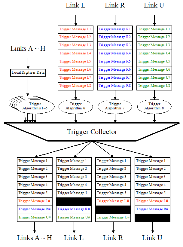
This is a legitimate setup because link L can be configured by writing to DGS's registers to use 'remote master' format, link R is natively 'remote master' format, and link U of DGS can be configured by writing to registers to use 'MyRIAD' format. This setup then means that the DGS master trigger has to somehow attempt to combine information not only from itself but from the other setups to make multi-system trigger accept messages. The overall data flow by which this occurs is shown in the following picture.
Currently Supported Cross-system Triggers
The important detail of the above picture is that the trigger messages coming in from links L, R and U must pass through Trigger Algorithms and only those combinations explicitly supported by the specific algorithms can create multi-detector coincidences. There are also limits, as indicated in the picture, of what trigger messages pass through to the other systems.
As the firmware is currently written there is no way to perform a three- or four-system coincidence and broadcast that coincidence trigger to all systems
Processing of information from other masters
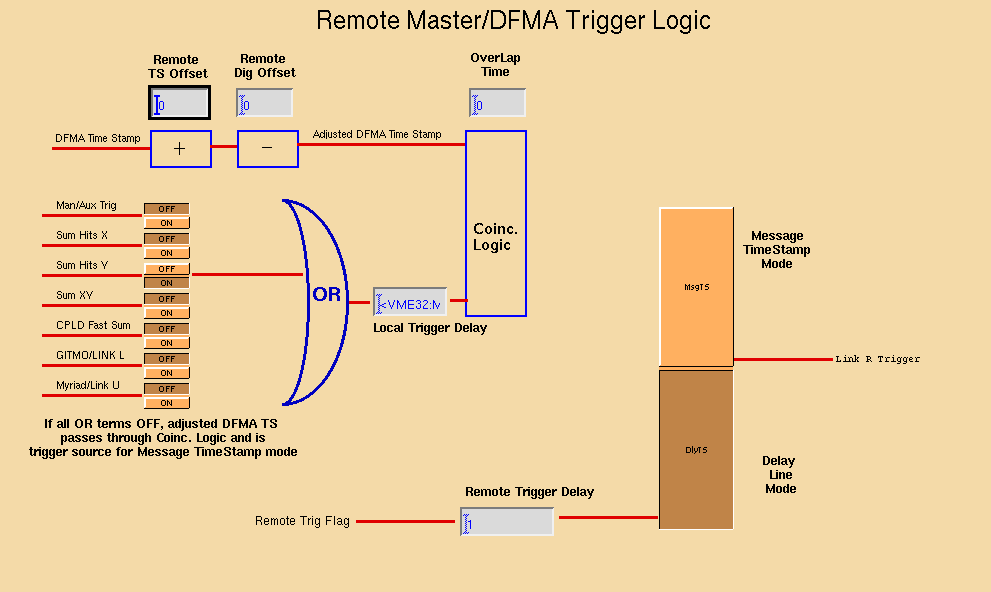
Whenever a SERDES link (L, R or U) is configured to be a 'remote master' data format, the firmware has a fixed way of processing that data, shown here.
As is seen in the picture, the algorithm can perform a coincidence calculation of the trigger message received from that particular link relative to any of the other triggers. The resultant coincidence then creates trigger acceptance messages FOR THAT LINK. This means that, in our example,
- DGS is receiving messages from the X-Array over link L. Thus, DGS can calculate a timestamp offset for the messages from the X-Array to compensate for time-of-flight, different integration time, etc., generate an internal pulse at the adjusted timestamp, and then perform a coincidence of that pulse with the other triggers at the moment they occur to generate an internal DGS trigger (algorithm #6).
- The Algorithm 6 trigger is sent to DGS, to DFMA and to the MyRIAD, but is not sent back to the X-Array to avoid infinite trigger loops
- DGS is receiving messages from DFMA over link R. Thus, DGS can calculate a timestamp offset for the messages from DFMA to compensate for time-of-flight, different integration time, etc., generate an internal pulse at the adjusted timestamp, and then perform a coincidence of that pulse with the other triggers at the moment they occur to generate an internal DGS trigger (algorithm #7).
- The Algorithm 7 trigger is sent to DGS, to X-Array and to the MyRIAD, but is not sent back to DFMA to avoid infinite trigger loops
The MyRIAD - link U in this example - is treated different.y.
