IOC Code Design
Intro
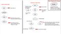
When an IOC (Input/Output Controller) has a pile of buffers from a digitizer or trigger module, each is pointed to by a pointer in one of three VxWorks queues:
- qFree
- qWritten
- qSender
The queues are lists of pointers that are used by the state machines inLoop, outLoop, and minisender to interact with the buffers. Each machine takes a pointer from a queue (if not empty) and uses the pointer to move data in/out of a buffer. When a machine is finished using the pointer to work with the buffer, the machine moves only the pointer from one queue to another. The state machines do not ever copy buffers.
State Machines
- inLoop: Takes a pointer from qFree, fills the buffer pointed to with VME data, then moves the pointer to qWritten.
- outLoop: Takes the pointer from qWritten, checks the data for sanity, and (if ok) moves the pointer to qSender.
- minisender: Waits for gtReceiver to ask for data. When this occurs, minisender takes a pointer from qSender, formats the buffer into packets, then sends it to gtReceiver. The pointer is returned to qFree when finished.
Flow Control Connections and Error Handling
Flow control is accomplished by modulating how inLoop fills buffers
inLoop:
Every time inLoop checks the digitizer, it looks at all the flags associated with the board-wide FIFO and reads the FIFO depth from the firmware.
- Will pause scanning for a variable time if the number of buffers in qFree < 10. The delay time is linearly proportional to the number of free buffers.
- Does not enforce any kind of flow control. Throttle should be used to ensure no events are needlessly dropped if the FIFO becomes too full, and inLoop must reset the FIFO to resynchronize to the event boundaries in the data.
- Requires that the digitizer firmware implements an event-bounded FIFO depth count (for versions newer than ~2019).
outLoop:
Checks buffers filled by inLoop for structure errors (does not start with 0xAAAAAAAA, length errors, timestamp of current event is later than timestamp of last event). There is a compile-time option as to whether or not outLoop will try to realign after a length error before continuing scanning, or just exit checking after the first error. These errors are counted, but they do not stop data from being passed from qWritten to qSender.
- Has no flow control connections.
- The support function CheckAndMoveBuffers will disable the transfer of buffers from qWritten to qSender if a software error results in no free buffers.
- In this state, prevents queue overrun by immediately recycling from qWritten back to qFree, resulting in loss of data in qWritten.
minisender:
Constantly polls for data request packets from gtReceiver. A zero length packet from gtReceiver is not considered an error and minisender will just retry continuously.
- Does not participate and does not respond to flow control.
Interface between State Machines and the control system (EPICS)
inLoop:
inLoop monitors and responds to the PVs Online_CS_StartStop, DAQBx_1_CS_Ena, DAQBx_2_CS_Ena, DAQx_3_CS_Ena, DAQBx_4_CS_Ena. It asserts data to the PVs VMEx:MDIG1_CV_Running, DAQCx_CV_InLoop1, and DAQCx_CV_InLoop2.
- VMEx:MDIG1_CV_Running is an internal communication PV between inLoop and outLoop. If set, outLoop understands that inLoop is running.
- DAQCx_CV_InLoop1 provides inLoop's measurement of the total Mbytes/sec it is transferring, for monitoring.
- DAQCx_CV_InLoop2 provides inLoop's measurement of the number of informational "type F" headers per second it is generating.
outLoop:
outLoop monitors and responds to the PVs Online_CS_SaveData, Online_CS_StartStop, VMEx:MDIG1_CV_Running, DAQCx_CS_TraceBd, DAQCx_CS_TraceChan, DAQCx_CS_TraceHorns. It asserts data to a large number of PVs
- DAQCV_CV_BuffersAvail and DAQCx_CV_NumSendBuffers are the buffer counts of qFree and qSender.
- DAQCx_CV_OutLoop1,2,3,4 are the number of lost buffers per digitizer.
- DAQCx_OL_DataRate0,1,2,3 are the read rates in kBytes/sec per digitizer.
- DAQCx_OL_Data0,1,2,3 are the total data amounts in Mbytes per digitizer.
- DAQCV_OL_NumxxBuffers report the number of buffer counts (xx = Written, xx = Lost).
- DAQCx_OL_BufLostPercent is what you think it is.
- DAQCx_CV_SendRate is the sender data rate in kbytes/sec.
- DAQCx_CV_TraceLen is the length of the diagnostic trace sent.
minisender:
minisender monitors and responds to the PVs Online_CS_StartStop and Online_CS_SaveData. It does not assert any monitoring or statistics data to PVs, as the load from outLoop covers everything.
IOC State Diagram for inLoop

Digitizer FIFO and Throttle
There are two FIFO depth counters in the digitizer. The "live depth" contains the actual exact count of how many words are in the FIFO. The "event bound depth" updates only when each full accepted event has been fully transferred to the FIFOs, so it lags behind the "live depth" by some fraction of an event at all times. inLoop uses the "event bound depth" when reading out the digitizer so that every buffer read by inLoop is guaranteed to always contain only full and complete events. This eliminates any need to waste CPU cycles trying to stitch together two parts of an event from different buffers. The digitizer can assert a "throttle request" bit to the trigger based upon any of the FIFO chip hardware flags or the programmable flag based upon the "live depth" counter. The "throttle request" stays on for as long as the condition persists.

The "Digitizer FIFO and Throttle" picture shows the board-wide FIFO buffer of the digitizer module and its relationship to the firmware. This piece of the firmware is global across all 10 channels. The readout machine shoves data into the FIFO (a separate pair of 16-bit wide chips outside the FPGA) whenever data from any channel is available. Inside all the channel data is 16 bits, but the readout machine takes pairs of words and writes them simultaneously into both FIFO chips to make the 32-bit words that the IOC reads out.
There is an ‘emergency stop’ built into the firmware that monitors the almost full flag bit of the FIFO. Assuming no shorted or open solder joints in the board, and assuming the firmware is working properly, this ensures that the FIFO can never actually go full. However, the almost full flag from the FIFO chips is at a fixed boundary that has no relationship to event boundaries, so letting the FIFO get to almost full is bad in that there will be a partial event at the end. If this occurs the digitizer must be reset. inLoop looks for this condition and should respond to it by issuing a Type F header with a subtype of 0xF, then automatically resetting the digitizer – however, there may be a one-line bug here in the IOC code that uses full, not almost full. This automatic reset will cause some data loss, but the digitizer will resynchonize.
Throttle within the Trigger
Every digitizer has one throttle bit it can assert to the router trigger, as each digitizer has only one board-wide FIFO. This can be set on a digitizer by digitizer basis using the x/16ths FIFO fullness selection to balance throttling between busy and not-busy digitizers.
Each router trigger has one throttle request bit it can assert to the master trigger. The router throttle request is the OR of all the digitizer throttle requests after applying assertion time filtering. Assertion time filtering is controlled by registers in each router trigger; the value defines the minimum number of 20.48usec periods that a digitizer’s throttle request must be continuously asserted before the router will deign to pass it on to the master trigger. The time filter value is global across all channels of the router.
The purpose of assertion time filtering is to prevent over-throttling of triggers from digitizers that are only in the throttle request state for very short times. Masked links cannot create throttle requests. The router trigger takes the OR of all filtered throttle requests. If the OR is ‘1’, then the router will assert a throttle request to the master trigger for a minimum time defined by a 2nd register.

The master trigger takes the OR of all throttle requests from the router triggers. This OR is a potential source of trigger veto but must be explicitly enabled by the end user. Inside the master trigger there is AND-OR logic for trigger veto that selectively enables which potential vetoes are allowed to make a veto (AND). The master trigger will not issue triggers if any of the allowed veto types occurs (OR), but the triggers are still calculated irrespective of veto. In the veto state all trigger types are blocked, there is no selective veto per trigger type.
The veto state lasts for as long as the OR of all enabled trigger vetoes is present, there is no minimum veto time. The master trigger’s diagnostic counters count both triggers that were issued and triggers that could have been issued, allowing estimation of the live time percentage by the ratio of the issuance rate divided by the calculated rate per trigger type.
Throttle: Putting it all Together
Initially the FIFO fullness threshold for assertion of the digitizer throttle request should be based upon the incoming data rate to the digitizer’s board-wide FIFO (event size per channel multiplied by event rate per channel multiplied by # of active channels) relative to the readout rate (assume 10Mbytes/sec divided by the number of digitizers in the crate). If the readout rate is sufficient, set the throttle threshold at 15/16th of the FIFO depth. But if the incoming rate exceeds the readout rate, the throttle threshold should be set at the depth of FIFO that the readout rate can support steady-state. This latter case is where the throttle is important.
With the throttle threshold appropriately set the throttle assertion time from a given digitizer can be estimated to be the time it takes to read out all the other digitizers in the crate. The router trigger throttle filtering time should then be set to about half this time so that the router trigger only passes “real” throttle requests and not transient requests on to the master trigger. The minimum router throttle assertion time to the master can typically be short as the router throttle assertion time should be determined mostly by digitizer settings.
Lastly, make certain that the master trigger is set to use the collected throttle request as a source of trigger veto. The system should then run smoothly.
If the system runs in fits and starts, or seems to be over-throttled, measurements with an oscilloscope can be taken using the NIM outputs of the trigger modules. NIM OUT 2 of any router trigger can be set to drive a copy of the time-filtered throttle request from any of the digitizers by use of a control register, allowing the activity from each digitizer to be examined. At the same time NIM_OUT1 can be configured to pulse any time a trigger accept occurs to verify that the master trigger is responding to the throttle.
The trigger modules implement diagnostic FIFOs in addition to the data FIFO that has TDC information. With appropriate software effort dumps of these diagnostic FIFOs can provide additional information. The trigger implements sixteen diagnostic FIFOs named CHAN_FIFO1 through CHAN_FIFO8, plus a second set MON_FIFO1 through MON_FIFO8. MON_FIFO7 is the TDC data FIFO. “CHAN” FIFOs monitor the individual SerDes links; “MON” FIFOs monitor board-wide actions. In the master trigger, MON_FIFO3 records a short record consisting of the bit-map of which router triggers are asserting throttle request and the current timestamp every time the bit-map of router throttle requests changes. The diagnostic FIFOs other than MON_FIFO7 are short, containing only 256 words each, but dumps of MON_FIFO3 can be used to diagnose whether throttle assertion times are rational from router to router. MON_FIFO3 has many other modes that alternatively monitor other trigger features, so proper setup before reading this FIFO is required.
Software Connections to the EPICS Control Code
- The readout machines inLoop.st, outLoop.st and MiniSender.st are all saved in the same source folder as all the rest of the DGS EPICS code is found: /global/devel/gretTop/9-22/dgsDriver/dgsDriverApp/src.
- The .st files have a set of support code files : inLoopSupport.c, outLoopSupport.c, SendReceiveSupport.c.
- There are a set of more general support files as well: profile.c (code execution profiling), QueueManagement.c (VxWorks queue routines), readDigFIFO.c (FIFO reader specific to digitizers) and readTrigFIFO.c (FIFO reader specific to triggers).
- The files devGdata.c and devGVME.c are the lowest-level data structure and VME read/write routines used by both the readout software and the EPICS software.
- there are two added .h files DGS_DEFS.h and DBG_PRINT_CONTROL.h whose #defined constants are used in the readout code.
- All files beginning with asyn... or drvAsyn... are the EPICS control and monitoring software that connect PVs to registers, but these do not directly affect anything in the readout code and the readout code does not directly affect anything in the control/monitoring code. Were it not for shared low-level VME access in devGdata.c and devGVME.c, and the specifically mentioned PV dependencies of the state machines listed earlier, readout code is effectively independent of control/monitoring code.
Some Things Similar to GammaWare
- File DGS_DEFS.h defines a C data structure “daqBoard” that contains a set of information about each board found in the VME crate.
- There is an array struct daqBoard daqBoards[GVME_MAX_CARDS] that creates an array of these data structures, so there’s one “daqBoard” data structure per board in the crate.
- This structure is similar in some respects to the Board[crate][slot] 2-d array of structures of GammaWare, although the underlying data structure here in the IOC is simpler than the one in GammaWare. Both enumerate all the registers in the board and provide some pointers such as the pointer to the FIFO data, so they have some common concepts.
Brief Comparison of EPICS Code: DGS IOC vs. SBX Pickoff
- The two EPICS implementations are seemingly much more different than they are alike, but that is driven by a PV database format design decision rather than by actual hardware/firmware differences.
- The DGS implementation for something you read will have a line of the form field(INP,"@asynMask($(PORT),0,0xaaaa2000,1)reg_board_id") to read a whole register, or field(INP,"@asynMask($(PORT),0,0xaaaa1010,1)reg_board_id") for a PV that reads some set of bits within a register.
- The SBX implementation for those same things will read field(INP, "#B0 C0x9D00 N29 A0 F0 @") for a whole register, or field(INP, "#B0 C0 N28 A0x0300 F8 @") for something that reads a group of bits. These achieve the same thing by different means. In the DGS version, the string asynMask($(PORT),0,0xaaaa2000,1)reg_board_id is parsed by C code that then does a search for reg_board_id in a list of register “parameters” stored in EPICS, and the coding 0xaaaa2000 means perform bit-group extraction (aaaa) of a field 32 bits long (20, it’s hex) starting at bit 0 (00). In the SBX version, the N29 A0 F0 part of the INP string means “register at address 29 (N29), use all bits (A0), don’t shift (F0).
- Both formats are extractable from an Excel spreadsheet describing the registers as implemented by the firmware, because in the end all that’s happening is that there’s a “field” that has a name, an address, a starting bit and a number of contiguous bits that the “field” represents.
- the latest version of the Excel spreadsheet Visual Basic for Applications code written this year uses formatting templates to extract out that same data in whatever text-substitution on a line-by-line basis you want, so it will work for both schemes.
A note from John Anderson: "I personally like the SBX model better as a hardware guy as the DGS model from Tim Madden seems to have a couple layers of excess indirection for no functional gain. However, after analyzing how it works, the conclusion is that there is no gain to be realized from changing it, but there’s risk of breaking stuff, so the risk/reward analysis conclusion is “don’t touch it”."
Compiling the Code (Skip here for commands to compile IOC code)
- Log into con6 as dgs
- cd /global/devel/gretTop/9-22/dgsIoc
- make -B
- cd ../dgsDrivers
- make -B
- cd ../dgsIoc
- make
- Log out of con6
- Log into dgs1 as dgs
- cd /global/devel/gretTop/9-22/dgsIoc
- ./Copy_from_sandbox.sh (This last command copies the munch file from con6 to dgs1, making it available to the MVME5500s.)
Code-Generated Headers
inLoop generates special headers in software that it injects into the data stream to provide useful information. All headers have a 4-bit header type code that has values from 0 to F (hexadecimal). inLoop-generated headers by fiat all have a type of 0xF, so are called “type F” headers. Furthering this definition, when readout of FIFOs from trigger modules is fully deployed the data from trigger modules will have type 0xE, or “type E” headers.
Digitizer firmware used from 2017 to 2021 has header types of 0x5 (LED) and 0x6 (CFD). Digitizer firmware released September 2021 uses type 0x7 (LED) and 0x8 (CFD).
All type 0xF headers have the same length but use bits 3:0 of word 1 as a header subtype. The subtype says why the header was generated. The GEO ADDR and PACKET DATA fields identify which board caused the type F header, and the timestamp identifies when the type F header was generated.

Code-Generated Headers for Trigger Modules
The master trigger module implements a time-to-digital converter (TDC) that provides a measurement of the delta-T between an external clock source applied to NIM input 2 relative to the clock of the master trigger itself. The TDC is implemented in firmware and is expected to provide ~500ps accuracy. Every time the signal at NIM input 2 has an edge the delta-T between edges is measured, but only those measurements that occur near trigger accepts are saved. The user selects one of the trigger algorithms of the master trigger to be the source of the TDC sampling, and a TDC sample is saved to a FIFO in the master trigger every time the selected algorithm fires.
The TDC data is provided as a set of data values related to four TDC sub-units that run at four phases of a 250MHz clock. Each phase is offset by ~1ns from the next. Each sub-unit has its own counter value that runs at the 250MHz clock plus a tapped delay line vernier that will record a “thermometer code” value (string of 1s followed by string of 0s) indicative of how far the edge of the input signal propagated down the delay line when the 250MHz clock sampled it. When a reading is taken a pipeline sequence of conversion logic takes the “thermometer code” and determines the numerical index of the delay line tap (0 to 63) that the edge propagated to. This value, plus the 250MHz counter, provides the interpolation data for that sub-unit. For all hits at least two sub-units will record a counter + vernier value and for the majority three sub-units will have valid values depending upon the exact timing of the input signal. To determine the time of the hit, the data from all four sub-units is examined, those not valid are discarded and those remaining are averaged. There are spreadsheets showing how the conversion to one time value is done.
Data read from the trigger module is only 16 bits wide. Every hit creates an event in the trigger FIFO that is fourteen 16-bit words long. The subroutines of readTrigFIFO.c will reformat that into a type E header of the format shown here.
