Global Control Screen
Jump to navigation
Jump to search
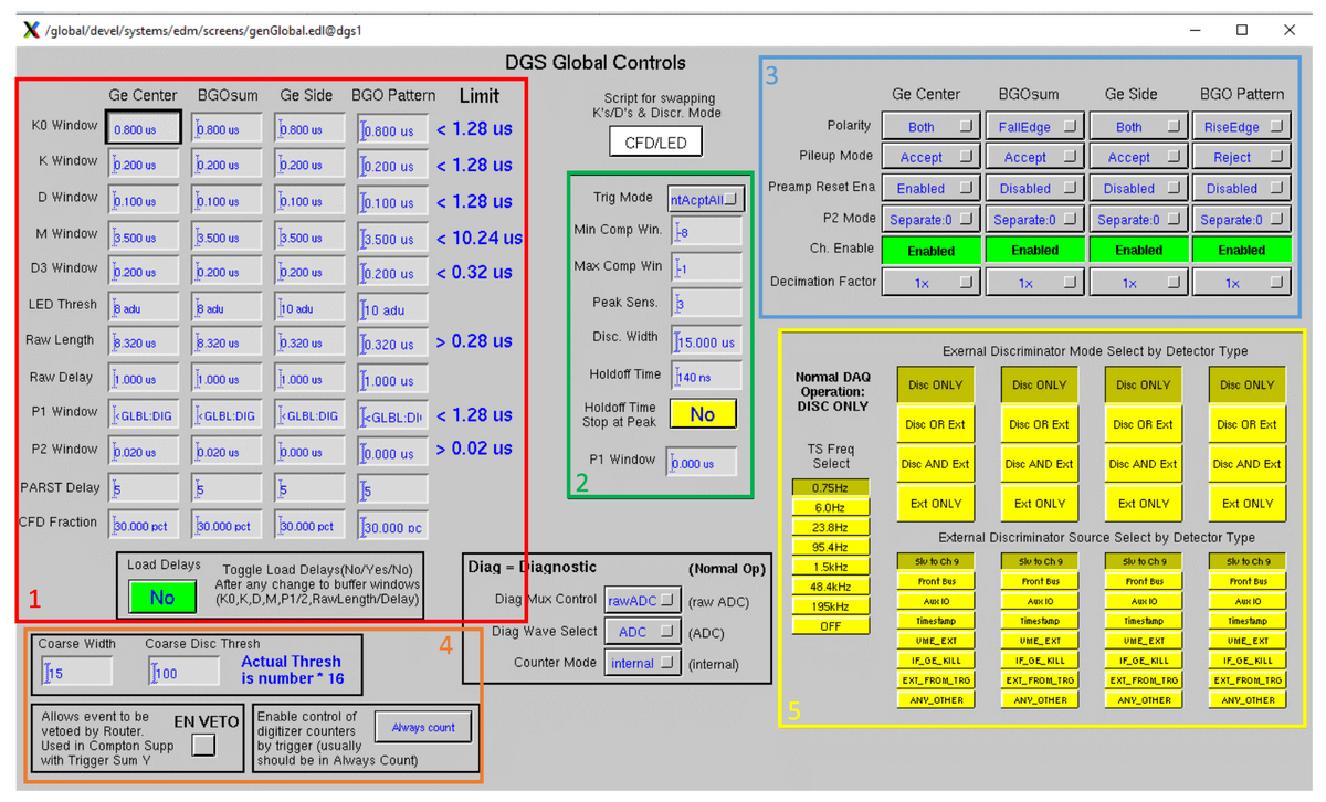
The global control screen allows a user to set control values that are written to all the digitizers in Gammasphere's DAQ system - in other words, it allows a user to specify the parameters of their desired waveform.
- Section 1 of the screen inside the red rectangle has four columns, each of which represent the different signals sent from detectors. The user sets these parameters so the time values can determine which signal shapes should be saved as waveform data, and how much of it should be saved. The threshold, PARST delay and CFD fraction are used to select how sensitive the digitizer is to the amplitude of the expected signals. Once all the values in the red section 1 are set, the user has to send a "load delays" command (the green button), which restarts the firmware and processes the data with the newly set values.
- Section 2 of the screen inside the green rectangle allows the user to set operational parameters for all the signals. The TrigMode, MinCompWin and MaxCompWin controls are the most commonly modified controls in this region. The TrigMode enables or disables the use of the trigger system to select specific events. TrigMode has two modes: IntAcptAll and TTCL. In the IntAcptAll mode, every AcceptedHit will get read out. In the TTCL mode, only the subset of AcceptedHits that meet the selection criteria of the trigger are read out. When this is selected, the MinCompWin and MaxCompWin controls select the time window relative to the timestamp contained within the Trigger Accept message during which events will be marked for readout. These timing values are related to the values of the “M Window”, “K0 window” and “K window”. The green parameters act immediately upon the user setting a new value (no “Load Delays” is required like in Section 1).
- Section 3 of the screen inside the blue rectangle encloses a separate set of controls that, like the red and green areas, control) how the digitizer channels process the analog data. These controls, however, are focused upon generic parameters that would apply to any signal as opposed to the other control parameters used to tune the response to specific timings and signal shapes.
- Section 4 of the screen inside the orange rectangle has to do with how the digitizer sends data to the trigger system and how the digitizer responds to the trigger system. Under normal circumstances the average user will never change these controls, the only exception is situations where setups are being used when only “clean” (non-scattered) gamma-ray hits should ever be read out. In this case the “EN VETO” box would be checked to allow the trigger system to automatically strip all “dirty” hits from the GeCenter/BGOsum channel pair before they can be selected for readout.
- Section 5 inside the yellow rectangle is used to control special operational modes of the digitizer channels, generally referred to as the “external discriminator”. The normal setting is “Disc ONLY” in which case the discriminator logic of each channel marks ‘hits’ only when edges of the input analog signal are found. The other settings allow selection of signals outside the channel (hence the name ‘external’) as an alternate source of the discriminator logic, and whether that external signal is ANDed, ORed, or used in place of the discriminator logic. The external discriminator modes are generally used only by experts to set up for unique situations, or to diagnose problems. Under normal experiment situations these controls are always set to “Disc ONLY”.
Go back to DGS Commander EDM Screens
