Digitizer IOCs: Difference between revisions
| Line 6: | Line 6: | ||
<imagemap> | <imagemap> | ||
Image:DigitizerIOC.PNG|frame|center|alt=Test Image Map | Image:DigitizerIOC.PNG|frame|center|alt=Test Image Map | ||
rect 1 | rect 1 1 345 149 [[What is an IOC]] | ||
rect 0 152 148 215 [[Monitor IOC process]] | |||
rect | rect 194 150 339 215 [[EPICS control of digitizers]] | ||
rect | rect 1 239 147 299 [[The scanning processes inLoop and outLoop]] | ||
rect 194 239 339 299 [[The Sender process]] | |||
rect | |||
rect | |||
</imagemap> | </imagemap> | ||
[[Threads versus source code structure]] | [[Threads versus source code structure]] | ||
Revision as of 21:47, September 16, 2021
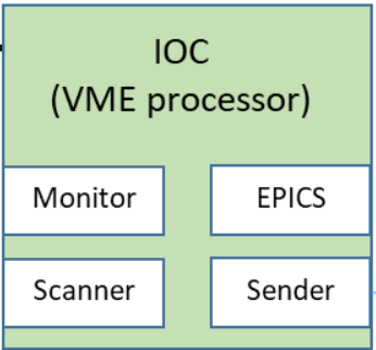
Digitizer IOCs
The IOC, or Input/Output Controller of a VME crate is an MVME5500E embedded processor module. The processors use the vxWorks operating system. VxWorks is capable of supporting multiple concurrent threads. The major thread types used in the Digital Gammasphere setup are shown in the white boxes within the picture of the IOC.
This is an image map. Click on section of picture to go to page for that item.

Threads versus source code structure
EPICS
EPICS, or the Experimental Physics and Industrial Control System, is the main thread that runs on the IOCs. EPICS implements a distributed database architecture in which a large number of Process Variables (PVs) are distributed across multiple processors. In Digital Gammasphere the mesh of processors consists of
- Eleven MVME5500s that each manage one VME backplane with four digitizer modules (VME01, VME02, ..., VME11)
- One MVME5500 that manages the VME backplane where the trigger modules are plugged in (VME32)
- The Linux computer DGS1, that is hosting two different processing threads related to EPICS:
- The "Soft IOC" program that acts like all the other IOCs, participating in the shared database; and
- The "DGSCommander" GUI that links GUI controls (buttons, indicators, drop-downs, graphs, etc.) to PVs in the distributed database.
When any of the VME-based IOC processors is rebooted, the boot script automatically initiates the EPICS thread and connects the processor to the portion of the database that is specific to that processor. The overall purpose of EPICS as implemented is to monitor whenever any PV value is changed (by the GUI or execution of a shell script) and to then report that to the entire database. Within each IOC, the EPICS thread there listens to those global reports. When a PV is changed, the specific IOC that has responsibility to react to a given PV (because that PV is in that IOCs part of the database) is then supposed to "do something" when the PV changes.
IOC response to a PV being changed
Exactly what the "do something" means is NOT part of EPICS. EPICS does not actually do any VME transactions. In any of the VME processors the EPICS thread sets a flag or updates a variable in response to a PV changing, but any action that is supposed to occur in response to a change in a PV is the responsibilty of a different thread. That thread is called the Control thread and is discussed below.
Within Digital Gammasphere, the process variables associated with a given VME crate are broken into three groups.
- Module-specific PVs have names of the form VMExx:<boardtype>xx:<name>. There are two sub-types of a module-specific PV.
- There are whole register PVs that are formatted like VME02:MDIG2:reg_LED_threshold5. As the name implies, changing the value of this PV will perform a simple write transaction, writing a single value to a single register in one board of one crate. The transaction overwrites the whole register.
- There are many registers in the firmware that contain multiple sub-fields (individual bits or a value that spans some few bits). In these cases, when the user changes the PV associated with that field, on the VME side the IOC has to do a read-modify-write transaction that changes just those bits while leaving the other bits of the register untouched.
- Crate-specific PVs have names of the form VMExx:CV These PVs are associated with control of the threads within the IOC processor and have no connection to any digitizer or trigger module.
How do I know what PVs are hosted by any given processor?
At the terminal window of any IOC you can type the command dbgrep followed by a search string (Linux regular expression) to list all PVs matching the search string. The search string should be enclosed in quotes.
vxWorks does not understand the Backspace key and thinks it is some weird character. It also doesn't understand the arrows or the delete key. In the vxWorks terminal window you use the key combination Ctrl-H as the backspace if you make a typing error.
There are many similar commands that can be typed in at the vxWorks prompt (or put into the startup script). The full list is found here. Besides dbgrep, the other two that should be noted are
- dbpf allows you to "put" a value to a PV. This is a manual way to change a PV. The identical functionality is also available at any Linux terminal window, but with a little different format. In Linux, the "put" function is done by typing caput <PV_name> <new value>.
- dbgf allows you to "get" the value of a PV. This polls the value of the PV in the database and prints it to the screen. The identical functionality is also available at any Linux terminal window, but with a little different format. In Linux, the "put" function is done by typing caget <PV_name>.
How IOCs change PVs
EPICS does not automatically update PVs. EPICS is just a processor-to-processor communication mechanism. There has to be a separate thread to collect system information and provide updates to the user through the GUI. We call this thread the Monitor thread, and it is discussed in detail below.
In the database, there is a completely separate set of EPICS process variables for displaying monitoring information to the user. Every register-level object in the firmware of each digitizer or trigger has a control PV and a matching readback PV. That is, the VME05:MDIG2:reg_CFD_fraction3 is the control PV, and it has a matching VME05:MDIG2:reg_CFD_fraction3_RBV readback PV. The "_RBV" stands for Read Back Value.
Why the duplication? The control PV allows the user to change the value in the register. The readback PV shows the user what is in the register. If you have a status register in the firmware - like a diagnostic counter or something that provides status bits about the hardware - this would be implemented as a read-only object. The user will want to see those values and changes in them, so the IOC must have a thread to poll them every so often so the user can see what's going on. For a normal read-write register in the firmware, monitoring the _RBV process variable provides confirmation that when the control PV was changed, the desired modification of the firmware register actually occurred.
The Control thread
The Control thread is the program within the IOC that actually "does something" in response to a notification from EPICS that a PV has changed. The Control thread simply translates changes in PVs to write transactions over VME. The Control thread is actually multiple threads, one per VME slot in the crate. Each of the Control threads has a list of 'parameters' associated with it, enumerating the subset of PVs the individual thread is responsible for. The use of these "parameters" allows for a centralized way of generating the databases for the different systems at ATLAS - see Generation of ATLAS DAQ systems for more information.
The Control thread has to handle PV changes in two different ways based upon the type of PV that has been changed. As noted above there are PVs for whole registers and PVs for fields within registers. Inside the firmware, of course, there are just whole registers. When a PV is changed the EPICS thread generates a short 'message' (really, just two 32-bit numbers) based upon the type of PV that has changed.
- If the PV is a whole-register PV, the EPICS thread sends a "message" of two 32-bit words where the first word is 0x<addr>0000 and the 2nd word is the value to write. The <addr> section of the 1st word (16 bits) is the 16-bit address offset of the register to write, relative to the base address of the board in the VME backplane. The VME hardware addressing scheme used in Digital Gammasphere is that every board's VME physical address is slot-based and a block of 65,536 VME addresses (16 bits) are allocated per-slot to each board.
- If the PV is a "field within register" PV, the EPICS thread sends a "message" of two 32-bit words where the first word is 0xAAAA<size><shift> and the 2nd word is the value to write (assuming the least significant bit of the field is bit 0). The <size> is the number of contiguous bits that the field spans, and the <shift> is the number of the bit where the least significant bit of the field starts. This requires an example to make sense.
- In the digitizer firmware there is a register at address 0x01C8 relative to the slot-based VME address of the board. Let's assume we're using the digitizer in slot 5 of crate 4. That means all the PVs will be of the form VME04:MDIG2:xxxxx because slot 5 is the 2nd master digitizer in crate 4. See VME crate numbering for more information.
- This particular register is called k_window2 and it is used to set the length of the K delay and the K0 delay of the processing pipeline for channel 2 of the digitizer.
- The value for the K delay is stored in bits 6:0 of the register. The value for the K0 delay is stored in bits 13:7 of the register. Bits 31:14 of the register are unused.
- We could write to the whole register by changing the value of the PV VME04:MDIG2:reg_k_window2 to the value 0x00000328. This would cause the EPICS thread to generate a message to the control thread with the values 0x01C80000 and 0x00000328. When this was written to the digitizer, the firmware would use bits 13:7 (binary 000110 , or 6 decimal) as the value for K0, and would use bits 6:0 (binary 0101000, or 40 decimal) as the value for K.
- Alternatively, one could set the PV VME04:MDIG2:k0_window2 to the value 10. Since this is a 'field' PV, the EPICS thread will generate the message 0xAAAA0707 and 0x0000000A because the field of interest starts at bit 7 and is 7 bits wide (13:7 is 7 bits). The control thread would then
- translate the value field from 0x0000000A to 0x00000500 by shifing the value 'A' left 7 bits.
- Read the value currently in the register
- Bit-by-bit AND the value read with 0xFFFF3F80 (all bits except bits 13:7 are set) to zero out the old value in bits 13:7
- Bit-by-bit OR the result of the AND with the value 0x00000500 to put in the new value in the field without affecting other bits in the register
- and then write that result back to the register.
The above is how every control operation for every register or field defined for every board in the system works, irrespective of board type. If firmware requires a more complex operation (e.g. a write to register X requires a 2nd write to some other register to "make it stick") those cases are coded into the specific source code for that particular type of board.
The Monitor thread
The converse of the Control thread that handles writing to hardware in response to changes in PVs, the Monitor thread is responsible for reading firmware register values at regular intervals and then updating the various VMExx:<boardtype>:<PVname)_RBV process variables. Just like there is one Control thread for each board in a crate, there is also one Monitor thread for each board in a crate.