Linking Systems Together
Linking Multiple Systems Together
The trigger logic implemented for the various DAQ systems and the hardware design of the trigger module allows for the possibility to link multiple systems together. This allows both clock synchronization and trigger sharing to occur. A number of rules must be obeyed, so read carefully.
Clock Sharing
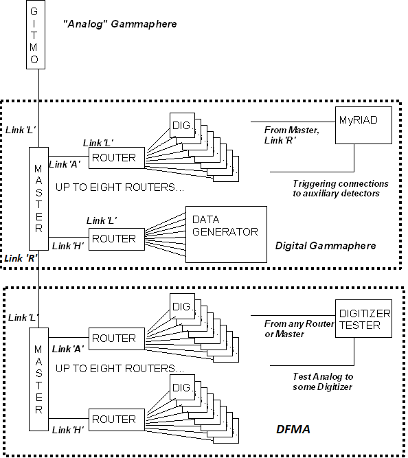
The basic method of clock sharing that most users are familiar with is that the master trigger sends clock to the routers, and the routers re-distribute that clock to the digitizers. Many users also understand that this tree of clock distribution has been extended to include Digital Gammasphere (DGS) sending the clock to DFMA, as shown here.
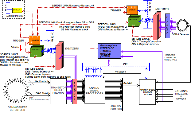
Those that have been involved from the beginning will recall that the DGS master trigger could also be connected to 'Analog' Gammasphere using the GITMO module - and use the clock from 'Analog' Gammasphere. Those that have been involved with hosting external detectors such as CHICO, Microball, ORRUBA, etc. also understand that there is clock sharing associated with the MyRIAD module. A more full picture of this clock distribution hierarchy is shown here.
The rules of the game as currently understood by users
So people know that you can hook a MyRIAD to DGS, and you can hook DFMA to DGS, and that with appropriate software incantations the clock and timestamp can be distributed from DGS to the other two systems. That is correct, and that is true, but it is not the whole and complete truth of how the firmware works.
How clock sharing REALLY works
How the clock sharing works in full detail is as follows.
- Any master trigger can be declared as the "timing monarch" that is the source of the clock.
- Which master trigger is the "timing monarch" is defined solely by cabling.
- If a master trigger has a cable connected to it's link L then that master trigger can be told to be subservient to whatever is on the other end of the link L cable.
- The hierarchy is defined by what cables plug into link L of what boards.
- This is why all the master-to-router cables go from any link of the master always to link L of the router.
- There is a limit as to how far the hierarchy can descend.
- Each time the clock is sent out of a board and received by another, clock jitter accumulates with each 'hop'.
- In the DGS-DFMA setup that people are used to, there are six 'hops' to get a trigger from DFMA back to DGS when DGS is the clock source :
- DGS to DFMA master -> DFMA master-router -> DFMA router-digitizer -> DFMA digitizer-router -> DFMA router-master -> DFMA master to DGS
- Measurements show that the accumulated jitter per 'hop' is about 35ps.
- So in the DGS-DFMA setup there would be a total accumulated jitter of (6*35), or 360ps.
- The serial data stream is 1Gbps, or 1ns (1000ps) per bit.
- If the ratio of the accumulated jitter divided by the bit period is greater than 50%, the link WILL HAVE BIT ERRORS.
- Thus the number of 'hops' in the current system is at a maximum and hanging a 3rd system behind DFMA will not work.
Any master trigger starts up using its own internal clock. Then, by writing a bit to a register, a master trigger agrees to use the clock that comes in on link L. The firmware has an automatic fallback provision that will cause any master trigger to fall back to using the internal clock irrespective of the software selection if there is no LOCK indication from the SERDES chip of link L. Thus it is necessary to establish the SERDES link between two master triggers and verify that link L is locked BEFORE telling the "subservient" master trigger to use the clock from link L.
Understanding Link usage
Each master trigger board has three "special" SERDES links named "L", "R" and "U". Originally this was meant to be read as "Left", "Right" and "Up" for drawing complicated link connections, but the convention of direction was abandoned unused. These three links are "special" in the sense that they are intended to be used as system interconnect links as opposed to the internal connections of links A through H. More precisely, what this means is that the data formats that these links send and receive are slightly different than the data format used to connect with routers. Each of these three links has a unique purpose and unique characteristics.
- Link L is unique in that it alone can receive a clock from an external source that can be used in place of the board's internal clock.
- Link L can receive two different data formats, either the GITMO format or the format from another master trigger.
- Link R is intended to receive data from another master trigger.
- Link U is historically used with the MyRIAD module to receive trigger information from an external detector.
- Link U can be programmed to receive data from another master trigger.
The concept of Propagation Control
Every master trigger is the master of its own detector. However, each master trigger that is receiving data from another master trigger from the SERDES links (L, R or U) can selectively propagate information received from another master trigger into itself. There is a Propagation Control register associated with each of the three links that is bit-wise mapped to enumerate what information is allowed to enter. This is described in the Trigger Timing and Control Link Specification document that I know you haven't read, so here's the text again.
6.4	Implementation of Selective Propagation (DGS/DFMA only)
The primary concern of selective propagation is the clock and the timestamp.  A control bit in every module of every type in this system determines whether the module runs from its own internal oscillator or from a clock received from an external source.  In the case of Trigger modules, an external clock may be received via Link L only.  However, when multiple detectors with multiple Master Triggers are chained together (for example. DGS/DFMA), a method must be defined to specify which Master is the source of Imperative Sync commands.
Three registers are implemented in DGS/DFMA Master Trigger firmware:
•	The Link L Propagation Control Register,
•	The Link R Propagation Control Register and
•	The Link U Propagation Control Register.
Bits within each register specify which frames of the TTCL data received from their associated link may be propagated into the local system from a remote source.  At power-up, these registers all initialize to zero, so that no propagation of remote data is allowed.  Each of the Propagation Control Registers is bit-mapped per-frame, as shown in Table 7.  Each bit, if set, enables the propagation of information from the indicated frame.
Bit=>	15	14	13	12	11	10	09	08	07	06	05	04	03	02	01	00
Name	F19	F18	F17	F16	F14	F12	F11	F10	F9	F8	F7	F6	F5	F4	F3	F1
Table 7 – General format of a Propagation Control Register
6.4.1	Sync Command Propagation
The ‘F1’ bit is only active for the Link L Propagation Control Register.  If the bit is set, then Imperative Sync commands received over Link L are propagated into the local system.  If the bit is clear, only the local Master may assert Imperative Sync.  Generally it is recommended that the F1 bit of each Master that receives a clock from another Master be set, so that there is a single module that can assert Imperative Sync throughout multiple detectors.
6.4.2	Trigger Command Propagation
The F3 through F10 bits, implemented in all three Propagation Control Registers, allow any subset of Trigger Decision frames from each link to be selectively re-propagated to the Routers and Digitizers of the local system. This allows for operation of multiple-detector experiments where the user may dynamically control which triggering conditions in each detector may cause triggers to occur within other detectors. As described in Section 7.3, re-propagated trigger decisions buffer up within their own FIFOs and are re-propagated during the last three Trigger Decision frames (Link L: Frame 8; Link R: Frame 9; Link U: Frame 10). To avoid the risk of deadly embrace, the command sequence sent out each of these three links (L, R, U) is coded so that a link may not re-propagate back the trigger decision frame assigned to itself.
6.4.3	Propagation of other command frames
Bits 15:9 of the Propagation Control Registers allow selective propagation of other command frames including frames currently defined as spares.
•	The F11, F18 and F19 bits are reserved for future use in case any of these spare frames are assigned specific functionality that may require re-propagation.
•	The F12 bit allows propagation of the Internal Trigger Frame (defined in section 7.5) from one detector to another.  Generally the Internal Trigger Frame is used in test stands, rather than running experiments, so this bit is not often used.
•	The F14 bit allows propagation of the Internal Trigger Frame defined in section 7.6.2.  This is useful in experiments where one or more Digitizer Tester modules have been added to generate “fake events” in some digitizer channels correlated to specific timestamps.
•	The F16 bit is expected to be the most commonly used propagation control bit other than the F1 bit.  When set, this bit allows re-propagation of the Synchronous System Capture Command defined in section 7.8.  With propagation of this command enabled, a single over-arching Master (or “Monarch”) may issue a single Synchronous System Capture Command and have it take effect throughout a multi-detector system.
•	The F17 bit, if set, allows propagation of Auxiliary Detector commands (see section 7.9).  Akin to the F16 bit, this allows control of auxiliary detector interfaces (MγRIADs) from a single top-level control point.
Timestamp sharing and Imperative Sync
There is a difference between sharing the CLOCK and sharing the TIMESTAMP. The timestamp logic of the subservient master trigger has a separate enable bit to allow the subservient master to respond to Imperative Sync commands sent from the "timing monarch". The precise rule here is:
- If the LINK L PROPAGATION CONTROL register, bit 0, is SET, and the subservient master has set its link L to be receiving commands from another master trigger, then the subservient master will respond only to Imperative Sync from the "timing monarch" AND cannot issue its own local Imperative Sync.
- If either of those two conditions are not met, then the subservient master, even if using the clock from the timing monarch, will IGNORE any Imperative Sync from the timing monarch but CAN issue its own Imperative Sync within its own system.

