SBX Power Board: Difference between revisions
No edit summary |
|||
| (4 intermediate revisions by the same user not shown) | |||
| Line 1: | Line 1: | ||
[[File:SBXPS.png|thumb| | [[File:SBXPS.png|thumb|600px|Figure 1]] | ||
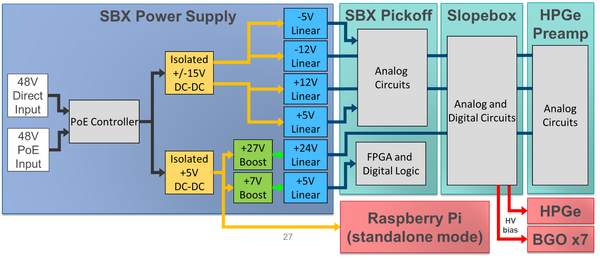
The power board of each SBX is an all-in-one, point-of-load power system for detectors and the SBX. It powers the entire system from a single 48VDC input by generating all voltages for slope box, preamp, pickoff board and Raspberry Pi. Furthermore, it allows a single detector and its SBX to be run entirely from one PoE (power over ethernet) port, enabling standalone detector operation. It is located on top of the [[The Pickoff Card|pickoff card]] inside the [[The Slope Box Extension|SBX]]. | The power board of each [[The Slope Box Extension|SBX]] is an all-in-one, point-of-load power system for detectors and the SBX. It powers the entire system from a single 48VDC input by generating all voltages for slope box, preamp, pickoff board and Raspberry Pi. Furthermore, it allows a single detector and its SBX to be run entirely from one PoE (power over ethernet) port, enabling standalone detector operation. It is located on top of the [[The Pickoff Card|pickoff card]] inside the [[The Slope Box Extension|SBX]]. | ||
Figure 1 shows how the Power Over Ethernet compliant allows a single detector plus SBX to be run entirely from one PoE port, enabling standalone detector operation. The Ethernet cable is plugged into the power board inside the SBX, and is used to power the slope box and pickoff, and preamp. An IOC within the SBX transfers signals to the digitizer, giving each detector the ability to run self-sufficiently. Furthermore, the Ethernet cable enables the user to view indicator values and control certain process variables using EPICS, which helps curate and monitor the data received. | Figure 1 shows how the Power Over Ethernet compliant allows a single detector plus SBX to be run entirely from one PoE port, enabling standalone detector operation. The Ethernet cable is plugged into the power board inside the SBX, and is used to power the slope box and pickoff, and preamp. An IOC within the SBX transfers signals to the digitizer, giving each detector the ability to run self-sufficiently. Furthermore, the Ethernet cable enables the user to view indicator values and control certain process variables using EPICS, which helps curate and monitor the data received. | ||
== | ==EDM Interface for Power Board== | ||
[[File:SBX screens.png|600px|thumb|Figure 2]] | [[File:SBX screens.png|600px|thumb|Figure 2]] | ||
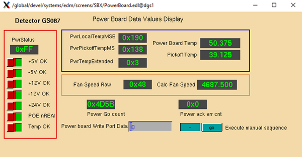
The power board of the SBX has the capability to control and indicate various process variables via | The power board of the SBX has the capability to control and indicate various process variables via [[DGS Commander EDM Screens|EDM]]. Figure 2 shows what the screen looks like. There are display values for temperature, power, and fan speed, and controls for power status and writing port data. | ||
Latest revision as of 21:36, March 22, 2023

The power board of each SBX is an all-in-one, point-of-load power system for detectors and the SBX. It powers the entire system from a single 48VDC input by generating all voltages for slope box, preamp, pickoff board and Raspberry Pi. Furthermore, it allows a single detector and its SBX to be run entirely from one PoE (power over ethernet) port, enabling standalone detector operation. It is located on top of the pickoff card inside the SBX.
Figure 1 shows how the Power Over Ethernet compliant allows a single detector plus SBX to be run entirely from one PoE port, enabling standalone detector operation. The Ethernet cable is plugged into the power board inside the SBX, and is used to power the slope box and pickoff, and preamp. An IOC within the SBX transfers signals to the digitizer, giving each detector the ability to run self-sufficiently. Furthermore, the Ethernet cable enables the user to view indicator values and control certain process variables using EPICS, which helps curate and monitor the data received.
EDM Interface for Power Board

The power board of the SBX has the capability to control and indicate various process variables via EDM. Figure 2 shows what the screen looks like. There are display values for temperature, power, and fan speed, and controls for power status and writing port data.