Nanoprobe Scanning Quick Reference
Back to X-Ray Microscopy
Chamber overview
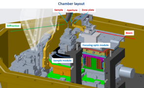
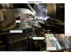
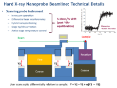
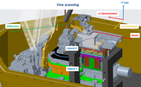
The Nanoprobe Instrument (NPI) consists of a Focusing Optics Module which holds a Fresnel zone plate that is integrated with a central beam stop. This optic focuses through a differentially adjustable Order Sorting Aperture (OSA) matched to the beam stop so that the primary unfocused beam is blocked either by the central stop or the OSA permitting only primary focus (first order) beam downstream of the aperture- this OSA stage is also mounted on the FOM allowing the combination to be moved simultaneously. The combination of these two elements focuses the beam onto the Sample Module that provides translational and rotational control of the sample position. Laser interferometry is used to track the X/Y position of both the optic and sample stages relative to a common reference frame, allowing the user to scan the fine position of the optic differentially locked in to the sample position which continuously corrects uncontrolled positional drift over the scan.
Coarse scanning
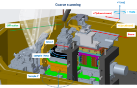
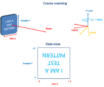
Coarse or overview scanning of fields of view 50um-1mm is typically done using the Sample Y motion and Atto Z (or whichever linear motion axis is most coplanar with the sample surface as mounted) - while the zone plate is left stationary in the "optic in" position. These scans result in an up/down flip relative to a top-down optical image as shown.
Notes:
i) Sample Y / Atto Z motions cannot be stepped less than 0.5um, for finer steps than that you will need to lock the hybrid motion and use fine scanning.
ii) Sample X motions (under the rotation stage) are disabled as this will move the center of rotation relative to the beam axis
iii) Coarse scanning Focus X / Focus Y is possible but should be avoided as this will move the optic out of the beam footprint, off the center of rotation, and out of focus simultaneously.
Fine scanning
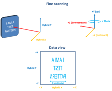
After a coarse position is chosen, fine scanning is typically used to make maps of field of view 200nm-20um. This scans the focusing optic module (Fresnel zone plate optic plus order sorting aperture) relative to the sample position differentially using piezo positioners locked in to the interferometric signal (smallest typical step ~5nm). When scanned from negative to positive there is a left/right flip relative to a top down optical view of the sample and the X direction is effectively compressed by the sample theta angle as shown.
Notes:
i) The X range should be kept to less than 30um to stay within the depth of focus at typical Bragg angles.
ii) The X/Y fine positioners are called "Hybrid nanopositioners" as if a call for motion is made that is out of the finite range of the piezos (~10um piezoY / 20um piezoX) then the piezo motion is ramped to the center of its range, a coarse motion is activated to place the new range center on the target position and then the piezo feedback loop is re-engaged to maintain position. This is done automatically but if the user would like to avoid stitching they should unlock the hybrid motion and manually drive to the desired scan center using Focus X/ Focus Y, and then keep the scans < 10um in width.
iii) The hybrid approach gives a continuous fine scanning range of up to 5mm for these positioners, however they will move out of focus and off the center of rotation with X movements > ~30um and will move the optic entirely out of the synchrotron beam footprint with movements>250um
iv) Movements of Sample theta and Atto X/Z are made inside the interferometric reference frame and so will result in motions of the sample without a change in hybrid X / hybrid Y readback value. Movements of Sample Y will be measured by the Hybrid Y readback value (as if the sample stage was drifting) and so typically the user will need to lock in at the NEW readback value coordinates after movement of Sample Y or it will effectively un-do the movement and might move the optic out of the beam
Focusing
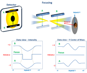
Focusing scans are typically made after an edge or isolated object has been found with fine scanning. These are 2D maps where the inner loop (either X or Y depending on the edge orientation) scans across the feature and the outer loop adjusts the Z position of the optic relative to the sample. Indications of reaching focus in these scans are object edges becoming sharper (peak to valley intensity ratio maximizing and contours between peak and valley minimizing) and observed center of mass / centroid motion inverting on the detector due to windowing
Notes:
i) The focalseries() command used for these scans introduces offsets in X and Y scaled to the Z distance to correct for alignment of the Z stage relative to the optical axis - if these scans are aborted the user should use the abort button on the scan window and wait patiently- ctrl C in the command line will NOT remove these additional positioners from the outer loop.
ii) Typical distances involved are ~300um Z distance (10 depth of focii) with an inner loop of ~2um Y distance but this may change depending on feature size and Z uncertainty
iii) When focusing on a round object 2D maps may be necessary at several focusZ positions, this can be done manually or with the panelfocus() command
iv) Typical signs of being out of focus are large centroid motions near object edges (L/R up/down), and sharp objects showing up as a series of donuts in a 2D map
Python Command Line Quick Reference
- Motion control
- mov(motor,position) Absolute motion of motor to specified position
- movr(motor,tweakvalue) Relative motion of motor by specified amount
- Motor definitions
