Nanoprobe Scanning Quick Reference: Difference between revisions
| (One intermediate revision by the same user not shown) | |||
| Line 43: | Line 43: | ||
===Diffraction with a nano-focused beam=== | ===Diffraction with a nano-focused beam=== | ||
[[File:Theta scan CTR.gif|frame|Diffraction images from theta series converted to 1D crystal truncation rod]] | [[File:Theta scan CTR.gif|frame|left|Diffraction images from theta series converted to 1D crystal truncation rod]] | ||
[[File:Theta scan RSM.gif|frame|Diffraction images from theta series converted to reciprocal space map]] | [[File:Theta scan RSM.gif|frame|Diffraction images from theta series converted to reciprocal space map]] | ||
</center> | |||
Bragg diffraction in the presence of a high numerical aperture focusing optic results in complex images created by a range of incident beam angles. These images can in certain cases be understood through a tilt series either imaging a broadened diffraction peak in a reciprocal space map or directly extracting the 1-D diffraction pattern directly from the far-field diffraction data. These demonstration scripts are loaded in the user Analysis directory and can be looked at with ctr_demo.m <br /> | Bragg diffraction in the presence of a high numerical aperture focusing optic results in complex images created by a range of incident beam angles. These images can in certain cases be understood through a tilt series either imaging a broadened diffraction peak in a reciprocal space map or directly extracting the 1-D diffraction pattern directly from the far-field diffraction data. These demonstration scripts are loaded in the user Analysis directory and can be looked at with ctr_demo.m <br /> | ||
'''Notes:'''<br /> | '''Notes:'''<br /> | ||
Latest revision as of 20:01, February 16, 2022
Back to X-Ray Microscopy
Chamber overview
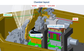
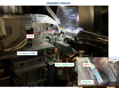
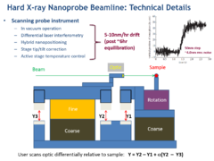
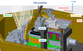
The Nanoprobe Instrument (NPI) consists of a Focusing Optics Module which holds a Fresnel zone plate that is integrated with a central beam stop. This optic focuses through a differentially adjustable Order Sorting Aperture (OSA) matched to the beam stop so that the primary unfocused beam is blocked either by the central stop or the OSA permitting only primary focus (first order) beam downstream of the aperture- this OSA stage is also mounted on the FOM allowing the combination to be moved simultaneously. The combination of these two elements focuses the beam onto the Sample Module that provides translational and rotational control of the sample position. Laser interferometry is used to track the X/Y position of both the optic and sample stages relative to a common reference frame, allowing the user to scan the fine position of the optic differentially locked in to the sample position which continuously corrects uncontrolled positional drift over the scan.
Coarse scanning
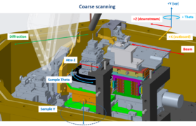
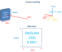
Coarse or overview scanning of fields of view 50um-1mm is typically done using the Sample Y motion and Atto Z (or whichever linear motion axis is most coplanar with the sample surface as mounted) - while the zone plate is left stationary in the "optic in" position. These scans result in an up/down flip relative to a top-down optical image as shown.
Notes:
i) Sample Y / Atto Z motions cannot be stepped less than 0.5um, for finer steps than that you will need to lock the hybrid motion and use fine scanning.
ii) Sample X motions (under the rotation stage) are disabled as this will move the center of rotation relative to the beam axis
iii) Coarse scanning Focus X / Focus Y is possible but should be avoided as this will move the optic out of the beam footprint, off the center of rotation, and out of focus simultaneously.
Fine scanning
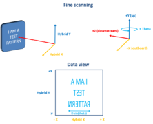
After a coarse position is chosen, fine scanning is typically used to make maps of field of view 200nm-20um. This scans the focusing optic module (Fresnel zone plate optic plus order sorting aperture) relative to the sample position differentially using piezo positioners locked in to the interferometric signal (smallest typical step ~5nm). When scanned from negative to positive there is a left/right flip relative to a top down optical view of the sample and the X direction is effectively compressed by the sample theta angle as shown.
Notes:
i) The X range should be kept to less than 30um to stay within the depth of focus at typical Bragg angles.
ii) The X/Y fine positioners are called "Hybrid nanopositioners" as if a call for motion is made that is out of the finite range of the piezos (~10um piezoY / 20um piezoX) then the piezo motion is ramped to the center of its range, a coarse motion is activated to place the new range center on the target position and then the piezo feedback loop is re-engaged to maintain position. This is done automatically but if the user would like to avoid stitching they should unlock the hybrid motion and manually drive to the desired scan center using Focus X/ Focus Y, and then keep the scans < 10um in width.
iii) The hybrid approach gives a continuous fine scanning range of up to 5mm for these positioners, however they will move out of focus and off the center of rotation with X movements > ~30um and will move the optic entirely out of the synchrotron beam footprint with movements>250um
iv) Movements of Sample theta and Atto X/Z are made inside the interferometric reference frame and so will result in motions of the sample without a change in hybrid X / hybrid Y readback value. Movements of Sample Y will be measured by the Hybrid Y readback value (as if the sample stage was drifting) and so typically the user will need to lock in at the NEW readback value coordinates after movement of Sample Y or it will effectively un-do the movement and might move the optic out of the beam
Focusing
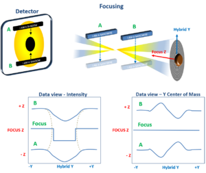
Focusing scans are typically made after an edge or isolated object has been found with fine scanning. These are 2D maps where the inner loop (either X or Y depending on the edge orientation) scans across the feature and the outer loop adjusts the Z position of the optic relative to the sample. Indications of reaching focus in these scans are object edges becoming sharper (peak to valley intensity ratio maximizing and contours between peak and valley minimizing) and observed center of mass / centroid motion inverting on the detector due to windowing
Notes:
i) The focalseries() command used for these scans introduces offsets in X and Y scaled to the Z distance to correct for alignment of the Z stage relative to the optical axis - if these scans are aborted the user should use the abort button on the scan window and wait patiently- ctrl C in the command line will NOT remove these additional positioners from the outer loop.
ii) Typical distances involved are ~300um Z distance (10 depth of focii) with an inner loop of ~2um Y distance but this may change depending on feature size and Z uncertainty
iii) When focusing on a round object 2D maps may be necessary at several focusZ positions, this can be done manually or with the panelfocus() command
iv) Typical signs of being out of focus are large centroid motions near object edges (L/R up/down), and sharp objects showing up as a series of donuts in a 2D map
Diffraction with a nano-focused beam
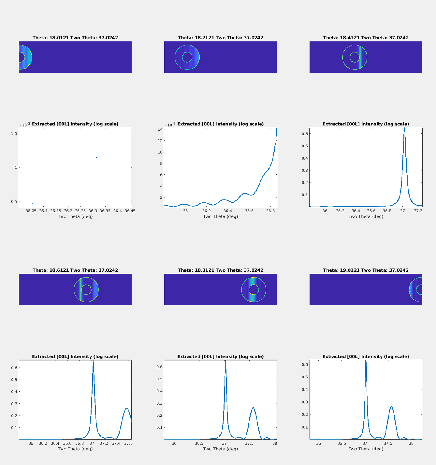
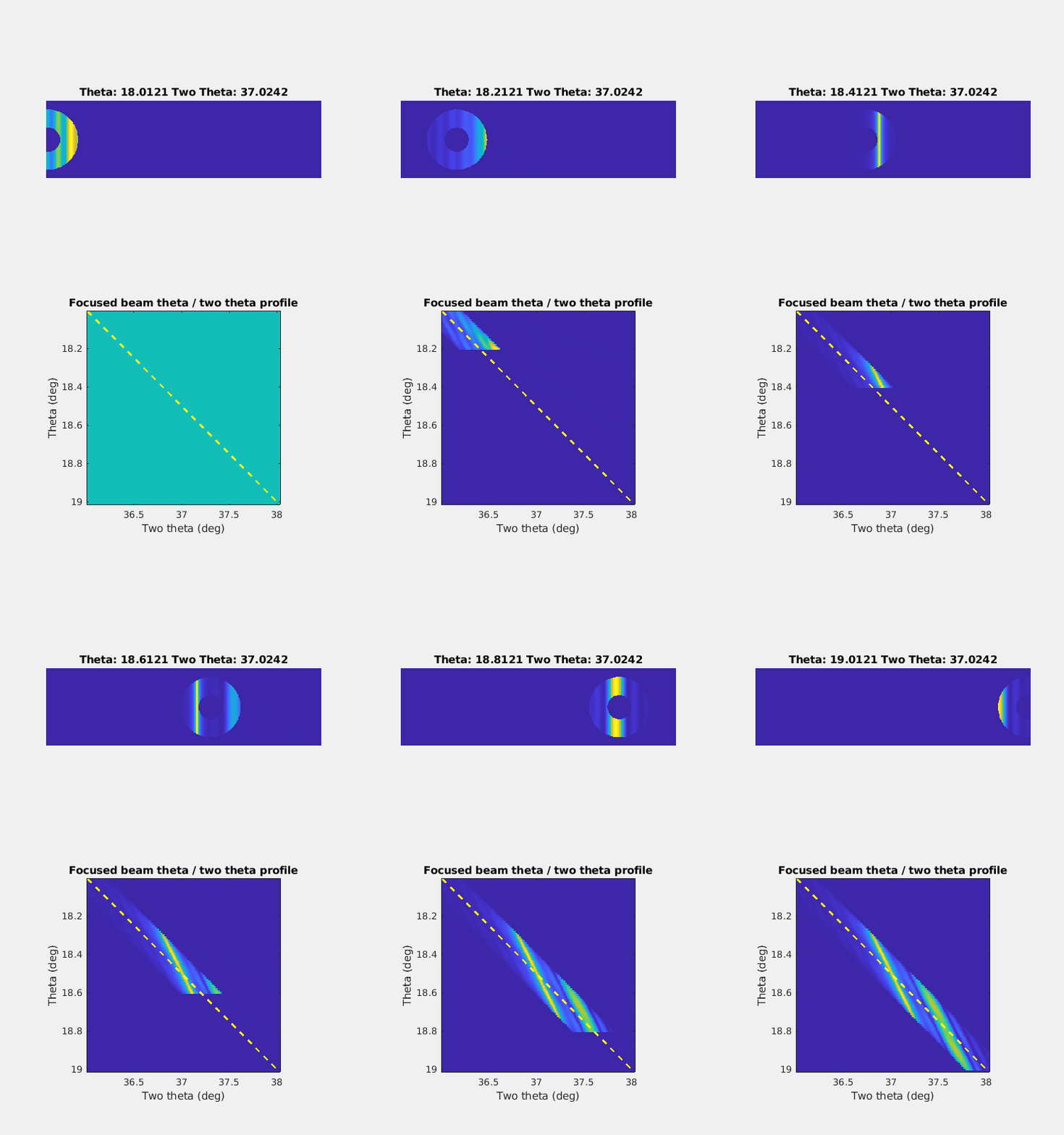
Bragg diffraction in the presence of a high numerical aperture focusing optic results in complex images created by a range of incident beam angles. These images can in certain cases be understood through a tilt series either imaging a broadened diffraction peak in a reciprocal space map or directly extracting the 1-D diffraction pattern directly from the far-field diffraction data. These demonstration scripts are loaded in the user Analysis directory and can be looked at with ctr_demo.m
Notes:
i) The CTR extraction analysis is essentially a ray-tracing method assuming perfect diffraction - this will not work near interfaces or in the presence of multiple diffraction peaks.
ii) Theta-x scans will need to be aligned to correct for horizontal runout before analyzing a tilt series per position
iii) Theta - two theta radial scans are also included
Python Command Line Quick Reference
- Motion control
| Motor name | Description | Use |
| hybridx / hybridy | X / Y fine scanning motion of the FZP optic | Differentially locked in fine scanning motions (steps>1nm) displacing the focused beam relative to the sample, lock-in is paused and coarse positioning is automatically called for command value outside of piezo range |
| fomx / fomy / fomz | X / Y / Z motions of the Focusing Optics Module | Coarse positioning (steps>0.5um) of the FOM stage moving both FZP optic and OSA |
| attox / samy / attoz | X / Y / Z motions of the Sample | Coarse positioning (steps>0.5um) of the sample, attox and attoz are on top of the sample rotation (samx and samz are below and disabled) |
| osax / osay / osaz | X / Y /Z motions of the Order Sorting Aperture | Coarse positioning of the OSA (30um diameter) in X/Y relative to the central stop of the FZP to reduce zeroth order background and avoid first order clipping, positioning in Z to avoid sample collision |
| twotheta / detgam | Two theta / Gamma motions of the diffraction detector | Angular motions of the detector within (two theta) and transverse to (gamma) the horizontal diffraction plane made at a fixed sample-detector distance |
| DCMenergy | Beam energy (ev) selected by the DCM | Typically used for spectroscopic scans across an elemental edge, should be scanned with the undulator motions to maintain flux over large ranges |
| Command syntax | Description | Use |
| mov(motor,position) | Absolute motion of motor to specified position | |
| movr(motor,tweakvalue) | Relative motion of motor by specified amount | |
| lock_hybrid() | Engages the differential piezo lock-in for fine scanning | Used after driving to a new coarse (samy/attoz) position to lock in at the current position (new differential coordinates) |
| unlock_hybrid() | Disengages the differential piezo lock-in | Used prior to coarse scanning or coarse motion of the sample to return the zone plate to the optical axis (in focus, on center of rotation) |
| defocus(z_move) | Activates a relative Z motion of the focusing optic stage simultaneously with a scaled hybridx and hybridy motion to maintain position | Used to change focal condition on a fixed spot, corrects for X/Y alignment of the Z motion relative to the optical axis |
- Microscope configuration
| Command syntax | Description | Use |
| zp_in() | Moves zone plate optic onto optical axis | Drives fomx/fomy/fomz to last set in-focus on-axis stage position |
| zp_out() | Moves zone plate optic away from optical axis | Drives fomx outboard to parallel beam pass-through position and fomz away from sample for surface visualization, unfocused diffraction or sample transfer |
| set_zp_in() | Sets current position to be new zp_in() position | Used after focus is established on a new sample or ROI |
| xrf_in() / xrf_out() | Moves inboard Vortex ME4 XRF detector to near-sample / far-from-sample position | Moved in for XRF from thin samples or theta >100deg, moved out for sample transfer |
| genie_in() | Moves downstream direct beam-imaging camera onto beam axis (moves medipix out) | Used prior to zp_out() to protect the medipix detector from exposure to the direct beam |
| medipix_in() | Moves downstream focused beam-imaging camera onto beam axis (moves genie out) | Used after zp_in() command to check OSA alignment and for downstream ptychography |
| prism_in() / prism_out() | Moves upstream prism onto beam axis enabling telescopic view of sample surface (BLOCKS X-RAYS) | Used after sample transfer for coarse visual alignment in zp_out() configuration |
| beamstop_in() / beamstop_out() | Moves downstream beamstop onto beam axis blocking transmitted beam from exiting chamber (BLOCKS GENIE/MEDIPIX) | Used to reduce background on EIGER diffraction detector from Be window rings and downstream air scattering |
| eiger_in(xoffset=0.0) / eiger_out() | Moves EIGER diffraction detector to a fixed close-to-chamber position with selectable two theta range / returns EIGER to scanning two theta mode | Used to identify multiple peaks simultaneously or to provide higher strain resolution on a single peak |
- Microscope scanning
| Command syntax | Description | Use |
| detectors(det_list) | Selects the active detectors that will trigger during scan | Current options are ['scaler','xrf','xrf_hscan','medipix','eiger'] |
| scan2d(motor1,startpos1,endpos1,numpts1,motor2,startpos2,endpos2,numpts2,dettime, absolute=False) | 2D step scan over a position range relative to current position with a selectable acquisition time, motor1 is the outer loop | Used to create a 2D real space image over a selectable field of view, or a 1D scan over a range of conditions such as beam energy or time delay |
| scan1d(motor,startpos,endpos,numpts,dettime, absolute=False) | 1D step scan over a linear position range relative to the current position with a selectable acquisition time | Used to find registration edges or optimize scattering with single motions |
| scan(is2d=0) | Activates EPICS scan record with currently configured parameters (linear scan is activated unless is2d=1) | Used to correctly activate pre-scan and post-scan data configuration and shutter control with an externally configured scan |
| focalseries(z_range,numptsz,y_range,numptsy,dettime,motor1=fomz,motor2=hybridy) | Shortcut 2D scan for focusing with Z motion in the outer loop and 1D hybrid motion (default hybridy) in inner loop | Used to focus on a local feature, X/Y corrections are introduced in outer loop to optimize Z motion parallel to optical axis |
| timeseries(numpts,dettime=1.0) | Shortcut 1D scan for multiple exposures over time made at a fixed position | Used to estimate damage thresholds or signal variation over time in response to an external variable such as temperature or field |
| theta2thetascan(thstartpos,thendpos,numpts,dettime) | 1D scan simultaneously scanning sample theta and detector two theta (at twice theta range) | Typically used with unfocused beam for CTR mapping |
| thetascan(thetapts,motor1,startpos1,endpos1,numpts1,motor2,startpos2,endpos2,numpts2,dettime) | Shortcut 3D scan for creating multiple 2D maps to be made over a set of Bragg theta angular positions | Used to create a rocking curve over a selectable field of view, alignment scans with a reference XRF channel can be created per point within this command |
| panelscan(ypositions,xpositions,motor1,startpos1,endpos1,numpts1,motor2,startpos2,endpos2,numpts2,dettime) | Shortcut for creating multiple 2D maps over a set of hybridy and hybridx positions | Used for "zoom in" fine scanning at multiple points of interest after a hybrid overview scan |
| tempscan(temppts,motor1,startpos1,endpos1,numpts1,motor2,startpos2,endpos2,numpts2,dettime) | Shortcut for multiple 2D maps made at different temperatures | Used with lakeshore temperature controller with editable wait time and sample vertical motion per temperature step |
| pvscan(pvname,pvpts,motor1,startpos1,endpos1,numpts1,motor2,startpos2,endpos2,numpts2,dettime) | Shortcut for creating multiple 2D maps while adjusting a selected process variable | Used for visualizing an area in response to an external variable such as temperature or field |
Sample change venting checklist
